

440
13 Metrology Technology of Lunar Lander
measured and the lunar lander coordinate system O 1 -X 1 Y 1 Z 1 was equivalent to the
relationship between O 2 -X 2 Y 2 Z 2 and O j -M 1 K 1 N 1 .
Because the RVS was small and the side plate was thin, it was impossible to install
the reference optical cubic prism. Therefore, the coordinates of several points on the
RVS antenna end surface should be measured to fit its normal direction. The practical measurement accuracy of theodolite was only 0.2 mm, so the fitting error for
normal direction of small aperture end surface was not adequate. Therefore, the laser
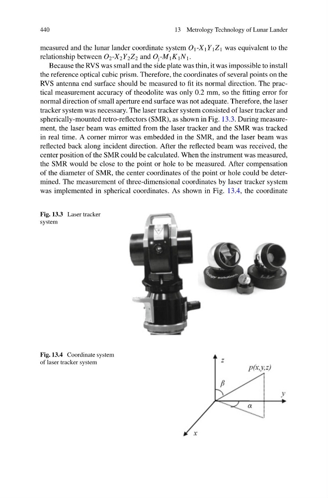
tracker system was necessary. The laser tracker system consisted of laser tracker and
spherically-mounted retro-reflectors (SMR), as shown in Fig. 13.3. During measurement, the laser beam was emitted from the laser tracker and the SMR was tracked
in real time. A corner mirror was embedded in the SMR, and the laser beam was
reflected back along incident direction. After the reflected beam was received, the
center position of the SMR could be calculated. When the instrument was measured,
the SMR would be close to the point or hole to be measured. After compensation
of the diameter of SMR, the center coordinates of the point or hole could be determined. The measurement of three-dimensional coordinates by laser tracker system
was implemented in spherical coordinates. As shown in Fig. 13.4, the coordinate
Fig. 13.3 Laser tracker
system
Fig. 13.4 Coordinate system
of laser tracker system
13 Metrology Technology of Lunar Lander
measured and the lunar lander coordinate system O 1 -X 1 Y 1 Z 1 was equivalent to the
relationship between O 2 -X 2 Y 2 Z 2 and O j -M 1 K 1 N 1 .
Because the RVS was small and the side plate was thin, it was impossible to install
the reference optical cubic prism. Therefore, the coordinates of several points on the
RVS antenna end surface should be measured to fit its normal direction. The practical measurement accuracy of theodolite was only 0.2 mm, so the fitting error for
normal direction of small aperture end surface was not adequate. Therefore, the laser
tracker system was necessary. The laser tracker system consisted of laser tracker and
spherically-mounted retro-reflectors (SMR), as shown in Fig. 13.3. During measurement, the laser beam was emitted from the laser tracker and the SMR was tracked
in real time. A corner mirror was embedded in the SMR, and the laser beam was
reflected back along incident direction. After the reflected beam was received, the
center position of the SMR could be calculated. When the instrument was measured,
the SMR would be close to the point or hole to be measured. After compensation
of the diameter of SMR, the center coordinates of the point or hole could be determined. The measurement of three-dimensional coordinates by laser tracker system
was implemented in spherical coordinates. As shown in Fig. 13.4, the coordinate
Fig. 13.3 Laser tracker
system
Fig. 13.4 Coordinate system
of laser tracker system