

13.4 Application of Special Measurement Technology
439
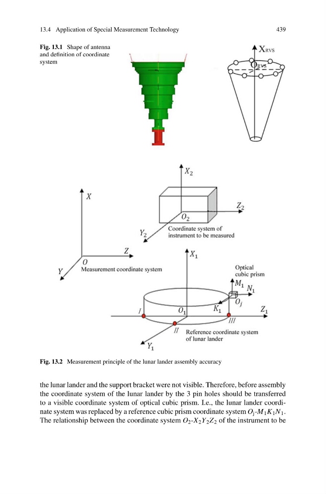
Fig. 13.1 Shape of antenna
and definition of coordinate
system
Fig. 13.2 Measurement principle of the lunar lander assembly accuracy
the lunar lander and the support bracket were not visible. Therefore, before assembly
the coordinate system of the lunar lander by the 3 pin holes should be transferred
to a visible coordinate system of optical cubic prism. I.e., the lunar lander coordinate system was replaced by a reference cubic prism coordinate system O j -M 1 K 1 N 1 .
The relationship between the coordinate system O 2 -X 2 Y 2 Z 2 of the instrument to be
439
Fig. 13.1 Shape of antenna
and definition of coordinate
system
Fig. 13.2 Measurement principle of the lunar lander assembly accuracy
the lunar lander and the support bracket were not visible. Therefore, before assembly
the coordinate system of the lunar lander by the 3 pin holes should be transferred
to a visible coordinate system of optical cubic prism. I.e., the lunar lander coordinate system was replaced by a reference cubic prism coordinate system O j -M 1 K 1 N 1 .
The relationship between the coordinate system O 2 -X 2 Y 2 Z 2 of the instrument to be