

11.6 Testing and Verification
393
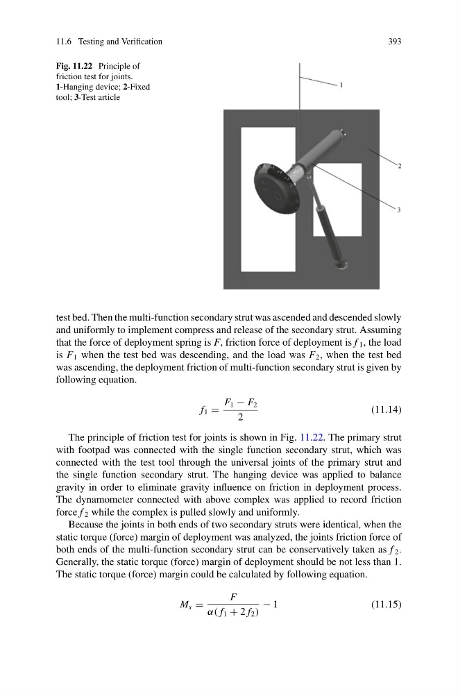
Fig. 11.22 Principle of
friction test for joints.
1-Hanging device; 2-Fixed
tool; 3-Test article
test bed. Then the multi-function secondary strut was ascended and descended slowly
and uniformly to implement compress and release of the secondary strut. Assuming
that the force of deployment spring is F, friction force of deployment is f 1 , the load
is F 1 when the test bed was descending, and the load was F 2 , when the test bed
was ascending, the deployment friction of multi-function secondary strut is given by
following equation.
f 1 =
F 1 − F 2
2
(11.14)
The principle of friction test for joints is shown in Fig. 11.22. The primary strut
with footpad was connected with the single function secondary strut, which was
connected with the test tool through the universal joints of the primary strut and
the single function secondary strut. The hanging device was applied to balance
gravity in order to eliminate gravity influence on friction in deployment process.
The dynamometer connected with above complex was applied to record friction
force f 2 while the complex is pulled slowly and uniformly.
Because the joints in both ends of two secondary struts were identical, when the
static torque (force) margin of deployment was analyzed, the joints friction force of
both ends of the multi-function secondary strut can be conservatively taken as f 2 .
Generally, the static torque (force) margin of deployment should be not less than 1.
The static torque (force) margin could be calculated by following equation.
M s =
F
α( f 1 + 2 f 2 )
− 1
(11.15)
393
Fig. 11.22 Principle of
friction test for joints.
1-Hanging device; 2-Fixed
tool; 3-Test article
test bed. Then the multi-function secondary strut was ascended and descended slowly
and uniformly to implement compress and release of the secondary strut. Assuming
that the force of deployment spring is F, friction force of deployment is f 1 , the load
is F 1 when the test bed was descending, and the load was F 2 , when the test bed
was ascending, the deployment friction of multi-function secondary strut is given by
following equation.
f 1 =
F 1 − F 2
2
(11.14)
The principle of friction test for joints is shown in Fig. 11.22. The primary strut
with footpad was connected with the single function secondary strut, which was
connected with the test tool through the universal joints of the primary strut and
the single function secondary strut. The hanging device was applied to balance
gravity in order to eliminate gravity influence on friction in deployment process.
The dynamometer connected with above complex was applied to record friction
force f 2 while the complex is pulled slowly and uniformly.
Because the joints in both ends of two secondary struts were identical, when the
static torque (force) margin of deployment was analyzed, the joints friction force of
both ends of the multi-function secondary strut can be conservatively taken as f 2 .
Generally, the static torque (force) margin of deployment should be not less than 1.
The static torque (force) margin could be calculated by following equation.
M s =
F
α( f 1 + 2 f 2 )
− 1
(11.15)