

354
10 TT&C and Telecommunication Technology …
The modulator digitally modulated the carrier with the telecommunication data
stream, amplified power with the power amplifier, and radiated to the ground with a
telecommunication antenna (the mid-gain antenna or the high-gain antenna). There
were two channels for telecommunication. During landing, the mid-gain antenna
could be selected by the microwave switch to transmit the telecommunication modulation signal. After landing, the high-gain antenna could be selected by the microwave
switch to transmit the telecommunication modulation signal rapidly to the ground.
10.4.4 Telecommunication Between Lunar Lander
and Lunar Rover
1. Telecommunication between the Lunar Lander and the Lunar Rover on Lunar
Surface
For the telecommunication requirement between the lunar lander and the lunar rover
on lunar surface, telecommunication instruments were onboard on the Chang’E-3
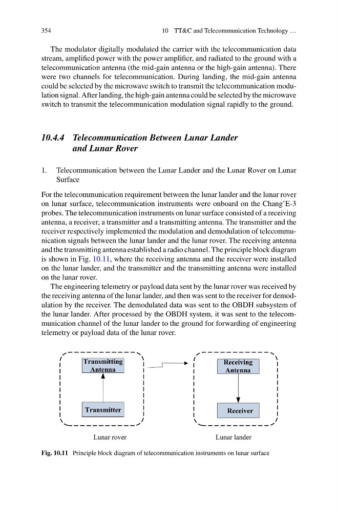
probes. The telecommunication instruments on lunar surface consisted of a receiving
antenna, a receiver, a transmitter and a transmitting antenna. The transmitter and the
receiver respectively implemented the modulation and demodulation of telecommunication signals between the lunar lander and the lunar rover. The receiving antenna
and the transmitting antenna established a radio channel. The principle block diagram
is shown in Fig. 10.11, where the receiving antenna and the receiver were installed
on the lunar lander, and the transmitter and the transmitting antenna were installed
on the lunar rover.
The engineering telemetry or payload data sent by the lunar rover was received by
the receiving antenna of the lunar lander, and then was sent to the receiver for demodulation by the receiver. The demodulated data was sent to the OBDH subsystem of
the lunar lander. After processed by the OBDH system, it was sent to the telecommunication channel of the lunar lander to the ground for forwarding of engineering
telemetry or payload data of the lunar rover.
Lunar rover
Lunar lander
Transmitting
Antenna
Transmitter
Receiving
Antenna
Receiver
Fig. 10.11 Principle block diagram of telecommunication instruments on lunar surface
10 TT&C and Telecommunication Technology …
The modulator digitally modulated the carrier with the telecommunication data
stream, amplified power with the power amplifier, and radiated to the ground with a
telecommunication antenna (the mid-gain antenna or the high-gain antenna). There
were two channels for telecommunication. During landing, the mid-gain antenna
could be selected by the microwave switch to transmit the telecommunication modulation signal. After landing, the high-gain antenna could be selected by the microwave
switch to transmit the telecommunication modulation signal rapidly to the ground.
10.4.4 Telecommunication Between Lunar Lander
and Lunar Rover
1. Telecommunication between the Lunar Lander and the Lunar Rover on Lunar
Surface
For the telecommunication requirement between the lunar lander and the lunar rover
on lunar surface, telecommunication instruments were onboard on the Chang’E-3
probes. The telecommunication instruments on lunar surface consisted of a receiving
antenna, a receiver, a transmitter and a transmitting antenna. The transmitter and the
receiver respectively implemented the modulation and demodulation of telecommunication signals between the lunar lander and the lunar rover. The receiving antenna
and the transmitting antenna established a radio channel. The principle block diagram
is shown in Fig. 10.11, where the receiving antenna and the receiver were installed
on the lunar lander, and the transmitter and the transmitting antenna were installed
on the lunar rover.
The engineering telemetry or payload data sent by the lunar rover was received by
the receiving antenna of the lunar lander, and then was sent to the receiver for demodulation by the receiver. The demodulated data was sent to the OBDH subsystem of
the lunar lander. After processed by the OBDH system, it was sent to the telecommunication channel of the lunar lander to the ground for forwarding of engineering
telemetry or payload data of the lunar rover.
Lunar rover
Lunar lander
Transmitting
Antenna
Transmitter
Receiving
Antenna
Receiver
Fig. 10.11 Principle block diagram of telecommunication instruments on lunar surface