

10.4 Design of Telemetry/Telecommand and Telecommunication Technology
353
On different launch windows, the pointing angle of the X-band mid-gain antenna
was different during powered descent. Therefore the configuration and beam
coverage of the X-band mid-gain antenna should be carefully designed to adapt
different launch windows. Analysis was conducted for predefined landing area, Sinus
Iridum and different launch windows. The half-beam angle of the X-band mid-gain
antenna was designed to meet the coverage requirement of Earth during powered
descent.
The high-gain antenna of the Chang’E-3 lunar lander was a fixed reflector antenna
driven by 2- DOF. After landing, the relationship between the ground station and the
Moon varied, so the high-gain antenna should be pointed to Earth by the driving
mechanism. The direction to Earth of the high-gain antenna was determined by the
pointing accuracy of the driving mechanism. The beam angle of the high-gain antenna
should not be less than the antenna pointing accuracy.
The pointing accuracy of the high-gain antenna of the lunar lander was determined
by various factors including the following aspects.
(1) Error of Earth station location: Earth was regarded as a point in orbit measurements because of the distance between Earth and the Moon. However in practice, there was a field angle of Earth when observed on lunar surface, which
could induce a reference error.
(2) Measurement error: orbital measurement error, ephemeris error, and attitude
measurement error.
(3) Open-loop control error of antenna orientation: there was the control error of
the high-gain antenna when it was pointed to a certain direction by bi-axis
driving mechanism.
The self-factors that affected pointing accuracy of the high gain antenna included
the installation accuracy of the high-gain antenna, the electromechanical axis error
of the RF component, the pointing error of the bi-axis driving mechanism, and the
thermal deformation error.
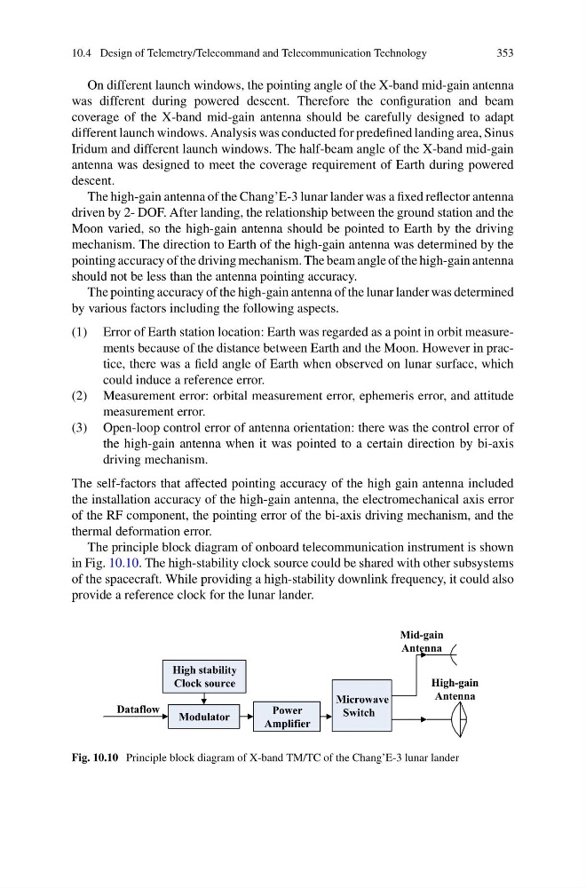
The principle block diagram of onboard telecommunication instrument is shown
in Fig. 10.10. The high-stability clock source could be shared with other subsystems
of the spacecraft. While providing a high-stability downlink frequency, it could also
provide a reference clock for the lunar lander.
Power
Amplifier
Modulator
High stability
Clock source
Mid-gain
Antenna
Microwave
Switch
Dataflow
High-gain
Antenna
Fig. 10.10 Principle block diagram of X-band TM/TC of the Chang’E-3 lunar lander
353
On different launch windows, the pointing angle of the X-band mid-gain antenna
was different during powered descent. Therefore the configuration and beam
coverage of the X-band mid-gain antenna should be carefully designed to adapt
different launch windows. Analysis was conducted for predefined landing area, Sinus
Iridum and different launch windows. The half-beam angle of the X-band mid-gain
antenna was designed to meet the coverage requirement of Earth during powered
descent.
The high-gain antenna of the Chang’E-3 lunar lander was a fixed reflector antenna
driven by 2- DOF. After landing, the relationship between the ground station and the
Moon varied, so the high-gain antenna should be pointed to Earth by the driving
mechanism. The direction to Earth of the high-gain antenna was determined by the
pointing accuracy of the driving mechanism. The beam angle of the high-gain antenna
should not be less than the antenna pointing accuracy.
The pointing accuracy of the high-gain antenna of the lunar lander was determined
by various factors including the following aspects.
(1) Error of Earth station location: Earth was regarded as a point in orbit measurements because of the distance between Earth and the Moon. However in practice, there was a field angle of Earth when observed on lunar surface, which
could induce a reference error.
(2) Measurement error: orbital measurement error, ephemeris error, and attitude
measurement error.
(3) Open-loop control error of antenna orientation: there was the control error of
the high-gain antenna when it was pointed to a certain direction by bi-axis
driving mechanism.
The self-factors that affected pointing accuracy of the high gain antenna included
the installation accuracy of the high-gain antenna, the electromechanical axis error
of the RF component, the pointing error of the bi-axis driving mechanism, and the
thermal deformation error.
The principle block diagram of onboard telecommunication instrument is shown
in Fig. 10.10. The high-stability clock source could be shared with other subsystems
of the spacecraft. While providing a high-stability downlink frequency, it could also
provide a reference clock for the lunar lander.
Power
Amplifier
Modulator
High stability
Clock source
Mid-gain
Antenna
Microwave
Switch
Dataflow
High-gain
Antenna
Fig. 10.10 Principle block diagram of X-band TM/TC of the Chang’E-3 lunar lander