

10.4 Design of Telemetry/Telecommand and Telecommunication Technology
347
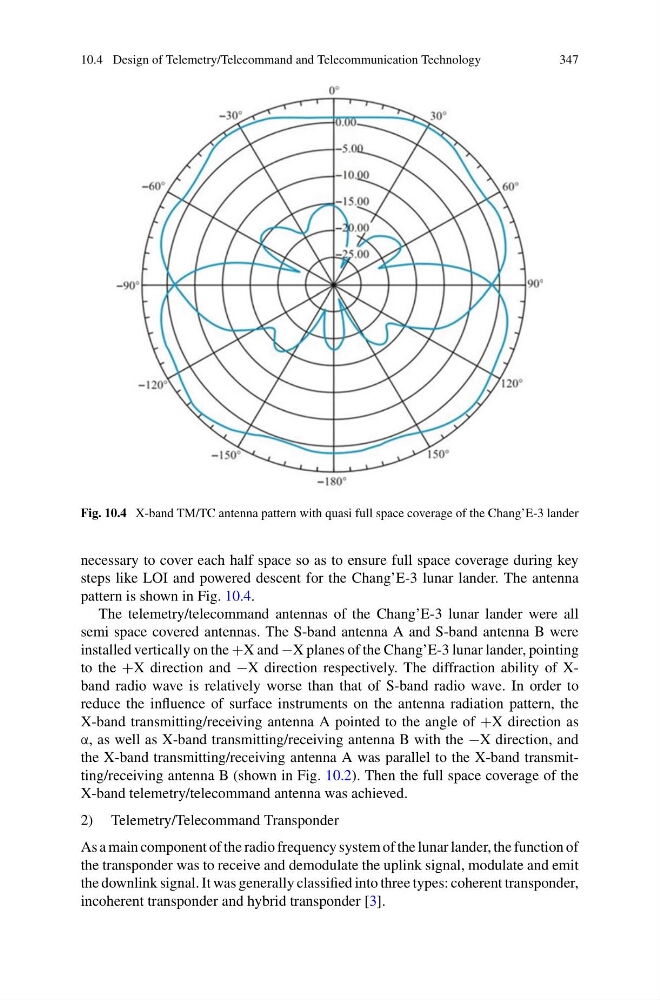
Fig. 10.4 X-band TM/TC antenna pattern with quasi full space coverage of the Chang’E-3 lander
necessary to cover each half space so as to ensure full space coverage during key
steps like LOI and powered descent for the Chang’E-3 lunar lander. The antenna
pattern is shown in Fig. 10.4.
The telemetry/telecommand antennas of the Chang’E-3 lunar lander were all
semi space covered antennas. The S-band antenna A and S-band antenna B were
installed vertically on the +X and −X planes of the Chang’E-3 lunar lander, pointing
to the +X direction and −X direction respectively. The diffraction ability of Xband radio wave is relatively worse than that of S-band radio wave. In order to
reduce the influence of surface instruments on the antenna radiation pattern, the
X-band transmitting/receiving antenna A pointed to the angle of +X direction as
α, as well as X-band transmitting/receiving antenna B with the −X direction, and
the X-band transmitting/receiving antenna A was parallel to the X-band transmitting/receiving antenna B (shown in Fig. 10.2). Then the full space coverage of the
X-band telemetry/telecommand antenna was achieved.
2) Telemetry/Telecommand Transponder
As a main component of the radio frequency system of the lunar lander, the function of
the transponder was to receive and demodulate the uplink signal, modulate and emit
the downlink signal. It was generally classified into three types: coherent transponder,
incoherent transponder and hybrid transponder [3].
347
Fig. 10.4 X-band TM/TC antenna pattern with quasi full space coverage of the Chang’E-3 lander
necessary to cover each half space so as to ensure full space coverage during key
steps like LOI and powered descent for the Chang’E-3 lunar lander. The antenna
pattern is shown in Fig. 10.4.
The telemetry/telecommand antennas of the Chang’E-3 lunar lander were all
semi space covered antennas. The S-band antenna A and S-band antenna B were
installed vertically on the +X and −X planes of the Chang’E-3 lunar lander, pointing
to the +X direction and −X direction respectively. The diffraction ability of Xband radio wave is relatively worse than that of S-band radio wave. In order to
reduce the influence of surface instruments on the antenna radiation pattern, the
X-band transmitting/receiving antenna A pointed to the angle of +X direction as
α, as well as X-band transmitting/receiving antenna B with the −X direction, and
the X-band transmitting/receiving antenna A was parallel to the X-band transmitting/receiving antenna B (shown in Fig. 10.2). Then the full space coverage of the
X-band telemetry/telecommand antenna was achieved.
2) Telemetry/Telecommand Transponder
As a main component of the radio frequency system of the lunar lander, the function of
the transponder was to receive and demodulate the uplink signal, modulate and emit
the downlink signal. It was generally classified into three types: coherent transponder,
incoherent transponder and hybrid transponder [3].