

18 Fault Isolation and Failure Analysis of 3D Packaging
609
4. Unbiased Highly Accelerated Stress Test (UHAST) and Biased Highly Accelerated Stress Test (BHAST) with high temperature and relative humidity to replicate
the harsh environment applications of devices.
Each reliability test initiate specific failure modes and mechanisms. For example,
PC test can cause “popcorn” or delamination between package interfaces due to large
pressure of vapors from adsorbed moisture or organic contaminations in packages,
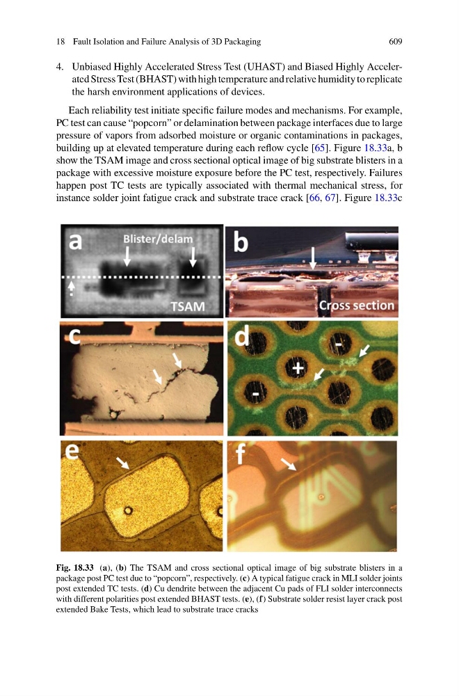
building up at elevated temperature during each reflow cycle [65]. Figure 18.33a, b
show the TSAM image and cross sectional optical image of big substrate blisters in a
package with excessive moisture exposure before the PC test, respectively. Failures
happen post TC tests are typically associated with thermal mechanical stress, for
instance solder joint fatigue crack and substrate trace crack [66, 67]. Figure 18.33c
Fig. 18.33 (a), (b) The TSAM and cross sectional optical image of big substrate blisters in a
package post PC test due to “popcorn”, respectively. (c) A typical fatigue crack in MLI solder joints
post extended TC tests. (d) Cu dendrite between the adjacent Cu pads of FLI solder interconnects
with different polarities post extended BHAST tests. (e), (f) Substrate solder resist layer crack post
extended Bake Tests, which lead to substrate trace cracks