

552
Y. Wang et al.
2.51
1.79
1.12
1.00
0.85
0.0
0.5
1.0
1.5
2.0
2.5
3.0
0~100
0~125
-55~110
-40~125
-40~150
Temperature range (
o
C)
Fatigue life ratio
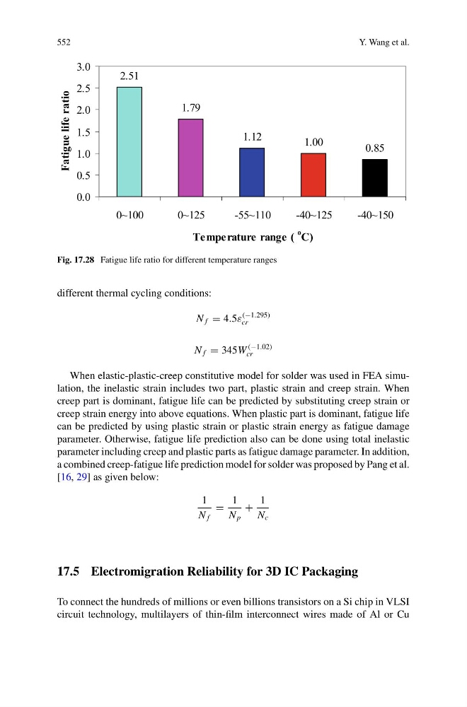
Fig. 17.28 Fatigue life ratio for different temperature ranges
different thermal cycling conditions:
N f = 4.5ε
(−1.295)
cr
N f = 345W
(−1.02)
cr
When elastic-plastic-creep constitutive model for solder was used in FEA simulation, the inelastic strain includes two part, plastic strain and creep strain. When
creep part is dominant, fatigue life can be predicted by substituting creep strain or
creep strain energy into above equations. When plastic part is dominant, fatigue life
can be predicted by using plastic strain or plastic strain energy as fatigue damage
parameter. Otherwise, fatigue life prediction also can be done using total inelastic
parameter including creep and plastic parts as fatigue damage parameter. In addition,
a combined creep-fatigue life prediction model for solder was proposed by Pang et al.
[16, 29] as given below:
1
N f
=
1
N p
+
1
N c
17.5 Electromigration Reliability for 3D IC Packaging
To connect the hundreds of millions or even billions transistors on a Si chip in VLSI
circuit technology, multilayers of thin-film interconnect wires made of Al or Cu
Y. Wang et al.
2.51
1.79
1.12
1.00
0.85
0.0
0.5
1.0
1.5
2.0
2.5
3.0
0~100
0~125
-55~110
-40~125
-40~150
Temperature range (
o
C)
Fatigue life ratio
Fig. 17.28 Fatigue life ratio for different temperature ranges
different thermal cycling conditions:
N f = 4.5ε
(−1.295)
cr
N f = 345W
(−1.02)
cr
When elastic-plastic-creep constitutive model for solder was used in FEA simulation, the inelastic strain includes two part, plastic strain and creep strain. When
creep part is dominant, fatigue life can be predicted by substituting creep strain or
creep strain energy into above equations. When plastic part is dominant, fatigue life
can be predicted by using plastic strain or plastic strain energy as fatigue damage
parameter. Otherwise, fatigue life prediction also can be done using total inelastic
parameter including creep and plastic parts as fatigue damage parameter. In addition,
a combined creep-fatigue life prediction model for solder was proposed by Pang et al.
[16, 29] as given below:
1
N f
=
1
N p
+
1
N c
17.5 Electromigration Reliability for 3D IC Packaging
To connect the hundreds of millions or even billions transistors on a Si chip in VLSI
circuit technology, multilayers of thin-film interconnect wires made of Al or Cu