

16 Processing and Reliability of Solder Interconnections …
517
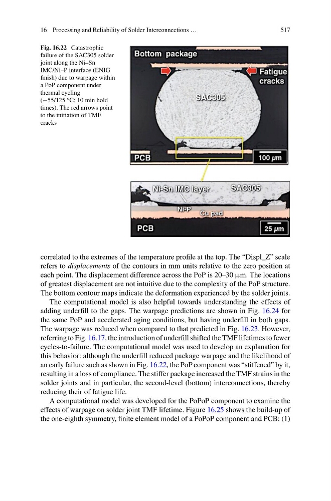
Fig. 16.22 Catastrophic
failure of the SAC305 solder
joint along the Ni–Sn
IMC/Ni–P interface (ENIG
finish) due to warpage within
a PoP component under
thermal cycling
(−55/125 °C; 10 min hold
times). The red arrows point
to the initiation of TMF
cracks
correlated to the extremes of the temperature profile at the top. The “Displ_Z” scale
refers to displacements of the contours in mm units relative to the zero position at
each point. The displacement difference across the PoP is 20–30 μm. The locations
of greatest displacement are not intuitive due to the complexity of the PoP structure.
The bottom contour maps indicate the deformation experienced by the solder joints.
The computational model is also helpful towards understanding the effects of
adding underfill to the gaps. The warpage predictions are shown in Fig. 16.24 for
the same PoP and accelerated aging conditions, but having underfill in both gaps.
The warpage was reduced when compared to that predicted in Fig. 16.23. However,
referring to Fig. 16.17, the introduction of underfill shifted the TMF lifetimes to fewer
cycles-to-failure. The computational model was used to develop an explanation for
this behavior: although the underfill reduced package warpage and the likelihood of
an early failure such as shown in Fig. 16.22, the PoP component was “stiffened” by it,
resulting in a loss of compliance. The stiffer package increased the TMF strains in the
solder joints and in particular, the second-level (bottom) interconnections, thereby
reducing their of fatigue life.
A computational model was developed for the PoPoP component to examine the
effects of warpage on solder joint TMF lifetime. Figure 16.25 shows the build-up of
the one-eighth symmetry, finite element model of a PoPoP component and PCB: (1)
517
Fig. 16.22 Catastrophic
failure of the SAC305 solder
joint along the Ni–Sn
IMC/Ni–P interface (ENIG
finish) due to warpage within
a PoP component under
thermal cycling
(−55/125 °C; 10 min hold
times). The red arrows point
to the initiation of TMF
cracks
correlated to the extremes of the temperature profile at the top. The “Displ_Z” scale
refers to displacements of the contours in mm units relative to the zero position at
each point. The displacement difference across the PoP is 20–30 μm. The locations
of greatest displacement are not intuitive due to the complexity of the PoP structure.
The bottom contour maps indicate the deformation experienced by the solder joints.
The computational model is also helpful towards understanding the effects of
adding underfill to the gaps. The warpage predictions are shown in Fig. 16.24 for
the same PoP and accelerated aging conditions, but having underfill in both gaps.
The warpage was reduced when compared to that predicted in Fig. 16.23. However,
referring to Fig. 16.17, the introduction of underfill shifted the TMF lifetimes to fewer
cycles-to-failure. The computational model was used to develop an explanation for
this behavior: although the underfill reduced package warpage and the likelihood of
an early failure such as shown in Fig. 16.22, the PoP component was “stiffened” by it,
resulting in a loss of compliance. The stiffer package increased the TMF strains in the
solder joints and in particular, the second-level (bottom) interconnections, thereby
reducing their of fatigue life.
A computational model was developed for the PoPoP component to examine the
effects of warpage on solder joint TMF lifetime. Figure 16.25 shows the build-up of
the one-eighth symmetry, finite element model of a PoPoP component and PCB: (1)