

16 Processing and Reliability of Solder Interconnections …
515
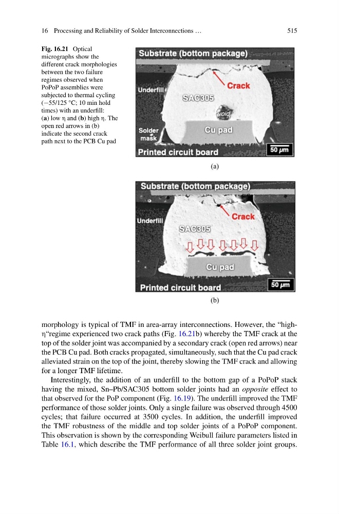
Fig. 16.21 Optical
micrographs show the
different crack morphologies
between the two failure
regimes observed when
PoPoP assemblies were
subjected to thermal cycling
(−55/125 °C; 10 min hold
times) with an underfill:
(a) low η and (b) high η. The
open red arrows in (b)
indicate the second crack
path next to the PCB Cu pad
morphology is typical of TMF in area-array interconnections. However, the “highη“regime experienced two crack paths (Fig. 16.21b) whereby the TMF crack at the
top of the solder joint was accompanied by a secondary crack (open red arrows) near
the PCB Cu pad. Both cracks propagated, simultaneously, such that the Cu pad crack
alleviated strain on the top of the joint, thereby slowing the TMF crack and allowing
for a longer TMF lifetime.
Interestingly, the addition of an underfill to the bottom gap of a PoPoP stack
having the mixed, Sn–Pb/SAC305 bottom solder joints had an opposite effect to
that observed for the PoP component (Fig. 16.19). The underfill improved the TMF
performance of those solder joints. Only a single failure was observed through 4500
cycles; that failure occurred at 3500 cycles. In addition, the underfill improved
the TMF robustness of the middle and top solder joints of a PoPoP component.
This observation is shown by the corresponding Weibull failure parameters listed in
Table 16.1, which describe the TMF performance of all three solder joint groups.
515
Fig. 16.21 Optical
micrographs show the
different crack morphologies
between the two failure
regimes observed when
PoPoP assemblies were
subjected to thermal cycling
(−55/125 °C; 10 min hold
times) with an underfill:
(a) low η and (b) high η. The
open red arrows in (b)
indicate the second crack
path next to the PCB Cu pad
morphology is typical of TMF in area-array interconnections. However, the “highη“regime experienced two crack paths (Fig. 16.21b) whereby the TMF crack at the
top of the solder joint was accompanied by a secondary crack (open red arrows) near
the PCB Cu pad. Both cracks propagated, simultaneously, such that the Cu pad crack
alleviated strain on the top of the joint, thereby slowing the TMF crack and allowing
for a longer TMF lifetime.
Interestingly, the addition of an underfill to the bottom gap of a PoPoP stack
having the mixed, Sn–Pb/SAC305 bottom solder joints had an opposite effect to
that observed for the PoP component (Fig. 16.19). The underfill improved the TMF
performance of those solder joints. Only a single failure was observed through 4500
cycles; that failure occurred at 3500 cycles. In addition, the underfill improved
the TMF robustness of the middle and top solder joints of a PoPoP component.
This observation is shown by the corresponding Weibull failure parameters listed in
Table 16.1, which describe the TMF performance of all three solder joint groups.