

16 Processing and Reliability of Solder Interconnections …
479
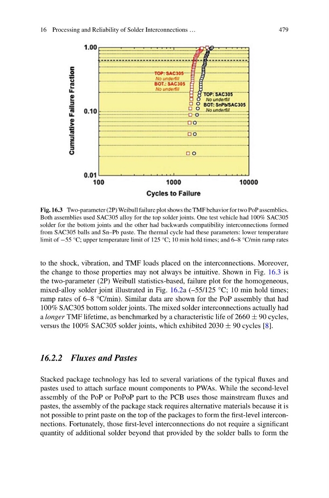
Fig. 16.3 Two-parameter (2P) Weibull failure plot shows the TMF behavior for two PoP assemblies.
Both assemblies used SAC305 alloy for the top solder joints. One test vehicle had 100% SAC305
solder for the bottom joints and the other had backwards compatibility interconnections formed
from SAC305 balls and Sn–Pb paste. The thermal cycle had these parameters: lower temperature
limit of −55 °C; upper temperature limit of 125 °C; 10 min hold times; and 6–8 °C/min ramp rates
to the shock, vibration, and TMF loads placed on the interconnections. Moreover,
the change to those properties may not always be intuitive. Shown in Fig. 16.3 is
the two-parameter (2P) Weibull statistics-based, failure plot for the homogeneous,
mixed-alloy solder joint illustrated in Fig. 16.2a (–55/125 °C; 10 min hold times;
ramp rates of 6–8 °C/min). Similar data are shown for the PoP assembly that had
100% SAC305 bottom solder joints. The mixed solder interconnections actually had
a longer TMF lifetime, as benchmarked by a characteristic life of 2660 ± 90 cycles,
versus the 100% SAC305 solder joints, which exhibited 2030 ± 90 cycles [8].
16.2.2 Fluxes and Pastes
Stacked package technology has led to several variations of the typical fluxes and
pastes used to attach surface mount components to PWAs. While the second-level
assembly of the PoP or PoPoP part to the PCB uses those mainstream fluxes and
pastes, the assembly of the package stack requires alternative materials because it is
not possible to print paste on the top of the packages to form the first-level interconnections. Fortunately, those first-level interconnections do not require a significant
quantity of additional solder beyond that provided by the solder balls to form the
479
Fig. 16.3 Two-parameter (2P) Weibull failure plot shows the TMF behavior for two PoP assemblies.
Both assemblies used SAC305 alloy for the top solder joints. One test vehicle had 100% SAC305
solder for the bottom joints and the other had backwards compatibility interconnections formed
from SAC305 balls and Sn–Pb paste. The thermal cycle had these parameters: lower temperature
limit of −55 °C; upper temperature limit of 125 °C; 10 min hold times; and 6–8 °C/min ramp rates
to the shock, vibration, and TMF loads placed on the interconnections. Moreover,
the change to those properties may not always be intuitive. Shown in Fig. 16.3 is
the two-parameter (2P) Weibull statistics-based, failure plot for the homogeneous,
mixed-alloy solder joint illustrated in Fig. 16.2a (–55/125 °C; 10 min hold times;
ramp rates of 6–8 °C/min). Similar data are shown for the PoP assembly that had
100% SAC305 bottom solder joints. The mixed solder interconnections actually had
a longer TMF lifetime, as benchmarked by a characteristic life of 2660 ± 90 cycles,
versus the 100% SAC305 solder joints, which exhibited 2030 ± 90 cycles [8].
16.2.2 Fluxes and Pastes
Stacked package technology has led to several variations of the typical fluxes and
pastes used to attach surface mount components to PWAs. While the second-level
assembly of the PoP or PoPoP part to the PCB uses those mainstream fluxes and
pastes, the assembly of the package stack requires alternative materials because it is
not possible to print paste on the top of the packages to form the first-level interconnections. Fortunately, those first-level interconnections do not require a significant
quantity of additional solder beyond that provided by the solder balls to form the