

15 Die and Package Level Thermal and Thermal/Moisture Stresses …
461
G∇
2 u i + (λ + G)ε, i −
E
1 − 2v
(ααT + βC) + p
, i +X i = 0
(15.29)
˙
ϕ = (1 − ϕ) ˙
u i, j
(15.30)
where D T is the thermal diffusivity. As normalized concentration is used, the equations can be solved for multi-material system such as 3D chip stacks. It is seen
that an integrated stress modeling during reflow soldering requires five types of
modeling, namely (1) moisture diffusion during moisture preconditioning and reflow,
(2) thermal modeling, (3) hygro-mechanical modeling, (4) thermo-mechanical
modeling, and (5) vapor pressure modeling.
15.4.6 Case Studies
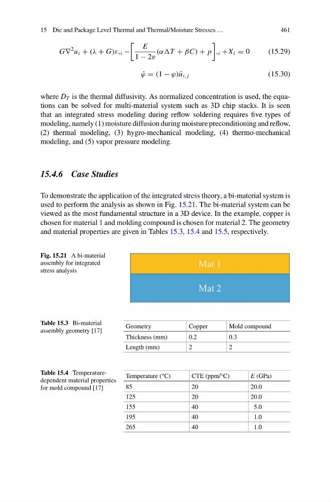
To demonstrate the application of the integrated stress theory, a bi-material system is
used to perform the analysis as shown in Fig. 15.21. The bi-material system can be
viewed as the most fundamental structure in a 3D device. In the example, copper is
chosen for material 1 and molding compound is chosen for material 2. The geometry
and material properties are given in Tables 15.3, 15.4 and 15.5, respectively.
Fig. 15.21 A bi-material
assembly for integrated
stress analysis
Table 15.3 Bi-material
assembly geometry [17]
Geometry
Copper
Mold compound
Thickness (mm)
0.2
0.3
Length (mm)
2
2
Table 15.4 Temperaturedependent material properties
for mold compound [17]
Temperature (°C)
CTE (ppm/°C)
E (GPa)
85
20
20.0
125
20
20.0
155
40
5.0
195
40
1.0
265
40
1.0
461
G∇
2 u i + (λ + G)ε, i −
E
1 − 2v
(ααT + βC) + p
, i +X i = 0
(15.29)
˙
ϕ = (1 − ϕ) ˙
u i, j
(15.30)
where D T is the thermal diffusivity. As normalized concentration is used, the equations can be solved for multi-material system such as 3D chip stacks. It is seen
that an integrated stress modeling during reflow soldering requires five types of
modeling, namely (1) moisture diffusion during moisture preconditioning and reflow,
(2) thermal modeling, (3) hygro-mechanical modeling, (4) thermo-mechanical
modeling, and (5) vapor pressure modeling.
15.4.6 Case Studies
To demonstrate the application of the integrated stress theory, a bi-material system is
used to perform the analysis as shown in Fig. 15.21. The bi-material system can be
viewed as the most fundamental structure in a 3D device. In the example, copper is
chosen for material 1 and molding compound is chosen for material 2. The geometry
and material properties are given in Tables 15.3, 15.4 and 15.5, respectively.
Fig. 15.21 A bi-material
assembly for integrated
stress analysis
Table 15.3 Bi-material
assembly geometry [17]
Geometry
Copper
Mold compound
Thickness (mm)
0.2
0.3
Length (mm)
2
2
Table 15.4 Temperaturedependent material properties
for mold compound [17]
Temperature (°C)
CTE (ppm/°C)
E (GPa)
85
20
20.0
125
20
20.0
155
40
5.0
195
40
1.0
265
40
1.0