

15 Die and Package Level Thermal and Thermal/Moisture Stresses …
453
small warpage because there is an initial warpage when curing the underfill material.
However, it is ideal to achieve a flat warpage curve versus temperature, as shown by
the test data in Fig. 15.15.
(3) Over-controlled warpage
In the preceding section for achieving warpage-free packaging, the die cap thickness
is selected by trial and error method through multiple rounds of simulations for
different package sizes. Here, an interesting phenomenon, called over-controlled
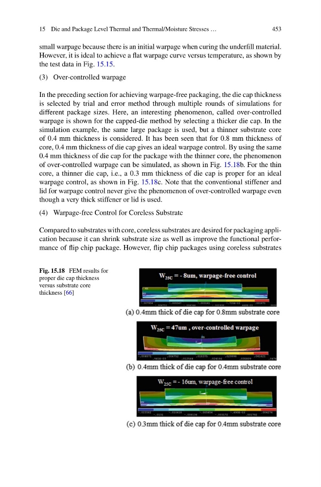
warpage is shown for the capped-die method by selecting a thicker die cap. In the
simulation example, the same large package is used, but a thinner substrate core
of 0.4 mm thickness is considered. It has been seen that for 0.8 mm thickness of
core, 0.4 mm thickness of die cap gives an ideal warpage control. By using the same
0.4 mm thickness of die cap for the package with the thinner core, the phenomenon
of over-controlled warpage can be simulated, as shown in Fig. 15.18b. For the thin
core, a thinner die cap, i.e., a 0.3 mm thickness of die cap is proper for an ideal
warpage control, as shown in Fig. 15.18c. Note that the conventional stiffener and
lid for warpage control never give the phenomenon of over-controlled warpage even
though a very thick stiffener or lid is used.
(4) Warpage-free Control for Coreless Substrate
Compared to substrates with core, coreless substrates are desired for packaging application because it can shrink substrate size as well as improve the functional performance of flip chip package. However, flip chip packages using coreless substrates
Fig. 15.18 FEM results for
proper die cap thickness
versus substrate core
thickness [66]
453
small warpage because there is an initial warpage when curing the underfill material.
However, it is ideal to achieve a flat warpage curve versus temperature, as shown by
the test data in Fig. 15.15.
(3) Over-controlled warpage
In the preceding section for achieving warpage-free packaging, the die cap thickness
is selected by trial and error method through multiple rounds of simulations for
different package sizes. Here, an interesting phenomenon, called over-controlled
warpage is shown for the capped-die method by selecting a thicker die cap. In the
simulation example, the same large package is used, but a thinner substrate core
of 0.4 mm thickness is considered. It has been seen that for 0.8 mm thickness of
core, 0.4 mm thickness of die cap gives an ideal warpage control. By using the same
0.4 mm thickness of die cap for the package with the thinner core, the phenomenon
of over-controlled warpage can be simulated, as shown in Fig. 15.18b. For the thin
core, a thinner die cap, i.e., a 0.3 mm thickness of die cap is proper for an ideal
warpage control, as shown in Fig. 15.18c. Note that the conventional stiffener and
lid for warpage control never give the phenomenon of over-controlled warpage even
though a very thick stiffener or lid is used.
(4) Warpage-free Control for Coreless Substrate
Compared to substrates with core, coreless substrates are desired for packaging application because it can shrink substrate size as well as improve the functional performance of flip chip package. However, flip chip packages using coreless substrates
Fig. 15.18 FEM results for
proper die cap thickness
versus substrate core
thickness [66]