

454
L. Chen et al.
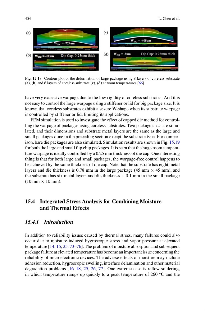
Fig. 15.19 Contour plot of the deformation of large package using 8 layers of coreless substrate
(a), (b) and 6 layers of coreless substrate (c), (d) at room temperatures [66]
have very excessive warpage due to the low rigidity of coreless substrates. And it is
not easy to control the large warpage using a stiffener or lid for big package size. It is
known that coreless substrates exhibit a severe W-shape when its substrate warpage
is controlled by stiffener or lid, limiting its applications.
FEM simulation is used to investigate the effect of capped die method for controlling the warpage of packages using coreless substrates. Two package sizes are simulated, and their dimensions and substrate metal layers are the same as the large and
small packages done in the preceding section except the substrate type. For comparison, bare die packages are also simulated. Simulation results are shown in Fig. 15.19
for both the large and small flip chip packages. It is seen that the huge room temperature warpage is ideally controlled by a 0.25 mm thickness of die cap. One interesting
thing is that for both large and small packages, the warpage-free control happens to
be achieved by the same thickness of die cap. Note that the substrate has eight metal
layers and die thickness is 0.78 mm in the large package (45 mm × 45 mm), and
the substrate has six metal layers and die thickness is 0.1 mm in the small package
(10 mm × 10 mm).
15.4 Integrated Stress Analysis for Combining Moisture
and Thermal Effects
15.4.1 Introduction
In addition to reliability issues caused by thermal stress, many failures could also
occur due to moisture-induced hygroscopic stress and vapor pressure at elevated
temperature [14, 15, 25, 73–76]. The problem of moisture absorption and subsequent
package failure at elevated temperature has become an important issue concerning the
reliability of microelectronic devices. The adverse effects of moisture may include
adhesion reduction, hygroscopic swelling, interface delamination and other material
degradation problems [16–18, 25, 26, 77]. One extreme case is reflow soldering,
in which temperature ramps up quickly to a peak temperature of 260 °C and the
L. Chen et al.
Fig. 15.19 Contour plot of the deformation of large package using 8 layers of coreless substrate
(a), (b) and 6 layers of coreless substrate (c), (d) at room temperatures [66]
have very excessive warpage due to the low rigidity of coreless substrates. And it is
not easy to control the large warpage using a stiffener or lid for big package size. It is
known that coreless substrates exhibit a severe W-shape when its substrate warpage
is controlled by stiffener or lid, limiting its applications.
FEM simulation is used to investigate the effect of capped die method for controlling the warpage of packages using coreless substrates. Two package sizes are simulated, and their dimensions and substrate metal layers are the same as the large and
small packages done in the preceding section except the substrate type. For comparison, bare die packages are also simulated. Simulation results are shown in Fig. 15.19
for both the large and small flip chip packages. It is seen that the huge room temperature warpage is ideally controlled by a 0.25 mm thickness of die cap. One interesting
thing is that for both large and small packages, the warpage-free control happens to
be achieved by the same thickness of die cap. Note that the substrate has eight metal
layers and die thickness is 0.78 mm in the large package (45 mm × 45 mm), and
the substrate has six metal layers and die thickness is 0.1 mm in the small package
(10 mm × 10 mm).
15.4 Integrated Stress Analysis for Combining Moisture
and Thermal Effects
15.4.1 Introduction
In addition to reliability issues caused by thermal stress, many failures could also
occur due to moisture-induced hygroscopic stress and vapor pressure at elevated
temperature [14, 15, 25, 73–76]. The problem of moisture absorption and subsequent
package failure at elevated temperature has become an important issue concerning the
reliability of microelectronic devices. The adverse effects of moisture may include
adhesion reduction, hygroscopic swelling, interface delamination and other material
degradation problems [16–18, 25, 26, 77]. One extreme case is reflow soldering,
in which temperature ramps up quickly to a peak temperature of 260 °C and the