

15 Die and Package Level Thermal and Thermal/Moisture Stresses …
451
15.3.6 Numerical Modeling for Optimizing Warpage Control
Design
Numerical simulation is used here to verify the effectiveness of the warpage control
method described above and also to optimize the cap design. FEM software ANSYS is
utilized to carry out the thermo-mechanical simulation. Several cases are investigated
and the results are given below.
(1) Comparison of different control methods
The same flip chip package used in the preceding test vehicle is used as an example for
FEM simulation. The stress-free temperature is assumed as the curing temperature
of 165 °C, at which the small warpage is not considered based on the test data. Four
package structures are compared, including bare die, stiffener, lid and capped-die
packages. The stiffener dimension is 0.6 mm thick and 7 mm wide, the lid dimension
is 1.5 mm thick and 4 mm foot width, and the die cap is 0.4 mm thick.
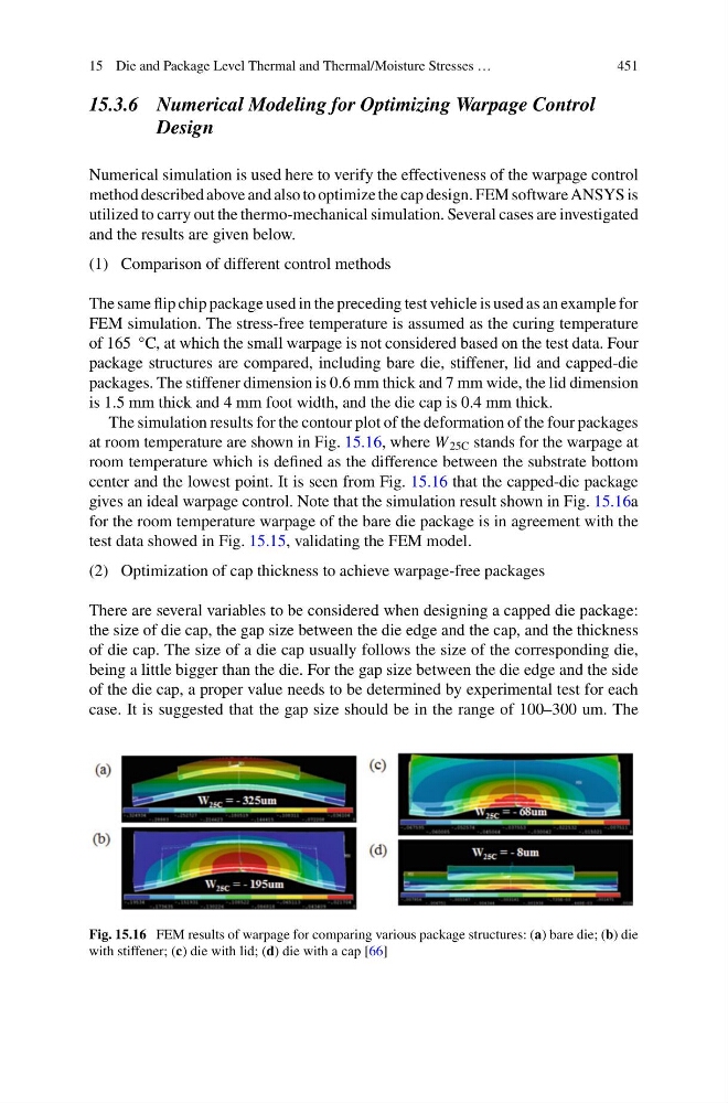
The simulation results for the contour plot of the deformation of the four packages
at room temperature are shown in Fig. 15.16, where W 25C stands for the warpage at
room temperature which is defined as the difference between the substrate bottom
center and the lowest point. It is seen from Fig. 15.16 that the capped-die package
gives an ideal warpage control. Note that the simulation result shown in Fig. 15.16a
for the room temperature warpage of the bare die package is in agreement with the
test data showed in Fig. 15.15, validating the FEM model.
(2) Optimization of cap thickness to achieve warpage-free packages
There are several variables to be considered when designing a capped die package:
the size of die cap, the gap size between the die edge and the cap, and the thickness
of die cap. The size of a die cap usually follows the size of the corresponding die,
being a little bigger than the die. For the gap size between the die edge and the side
of the die cap, a proper value needs to be determined by experimental test for each
case. It is suggested that the gap size should be in the range of 100–300 um. The
Fig. 15.16 FEM results of warpage for comparing various package structures: (a) bare die; (b) die
with stiffener; (c) die with lid; (d) die with a cap [66]
451
15.3.6 Numerical Modeling for Optimizing Warpage Control
Design
Numerical simulation is used here to verify the effectiveness of the warpage control
method described above and also to optimize the cap design. FEM software ANSYS is
utilized to carry out the thermo-mechanical simulation. Several cases are investigated
and the results are given below.
(1) Comparison of different control methods
The same flip chip package used in the preceding test vehicle is used as an example for
FEM simulation. The stress-free temperature is assumed as the curing temperature
of 165 °C, at which the small warpage is not considered based on the test data. Four
package structures are compared, including bare die, stiffener, lid and capped-die
packages. The stiffener dimension is 0.6 mm thick and 7 mm wide, the lid dimension
is 1.5 mm thick and 4 mm foot width, and the die cap is 0.4 mm thick.
The simulation results for the contour plot of the deformation of the four packages
at room temperature are shown in Fig. 15.16, where W 25C stands for the warpage at
room temperature which is defined as the difference between the substrate bottom
center and the lowest point. It is seen from Fig. 15.16 that the capped-die package
gives an ideal warpage control. Note that the simulation result shown in Fig. 15.16a
for the room temperature warpage of the bare die package is in agreement with the
test data showed in Fig. 15.15, validating the FEM model.
(2) Optimization of cap thickness to achieve warpage-free packages
There are several variables to be considered when designing a capped die package:
the size of die cap, the gap size between the die edge and the cap, and the thickness
of die cap. The size of a die cap usually follows the size of the corresponding die,
being a little bigger than the die. For the gap size between the die edge and the side
of the die cap, a proper value needs to be determined by experimental test for each
case. It is suggested that the gap size should be in the range of 100–300 um. The
Fig. 15.16 FEM results of warpage for comparing various package structures: (a) bare die; (b) die
with stiffener; (c) die with lid; (d) die with a cap [66]