

15 Die and Package Level Thermal and Thermal/Moisture Stresses …
449
for bonding the die cap with the die may use high conductive fillers, such as silver
flakes. Generally, the capped-die approach can be used to protect 3D chip stacks
from large warpage, where a cap can be made to constrain the deformation of the
stacking dies on a large organic substrate.
15.3.5 Warpage Characterization by Experimental Testing
Experimental testing by shadow moiré technique can be used to characterize the
warpage deformation and evaluate the warpage control methods. Here we compare
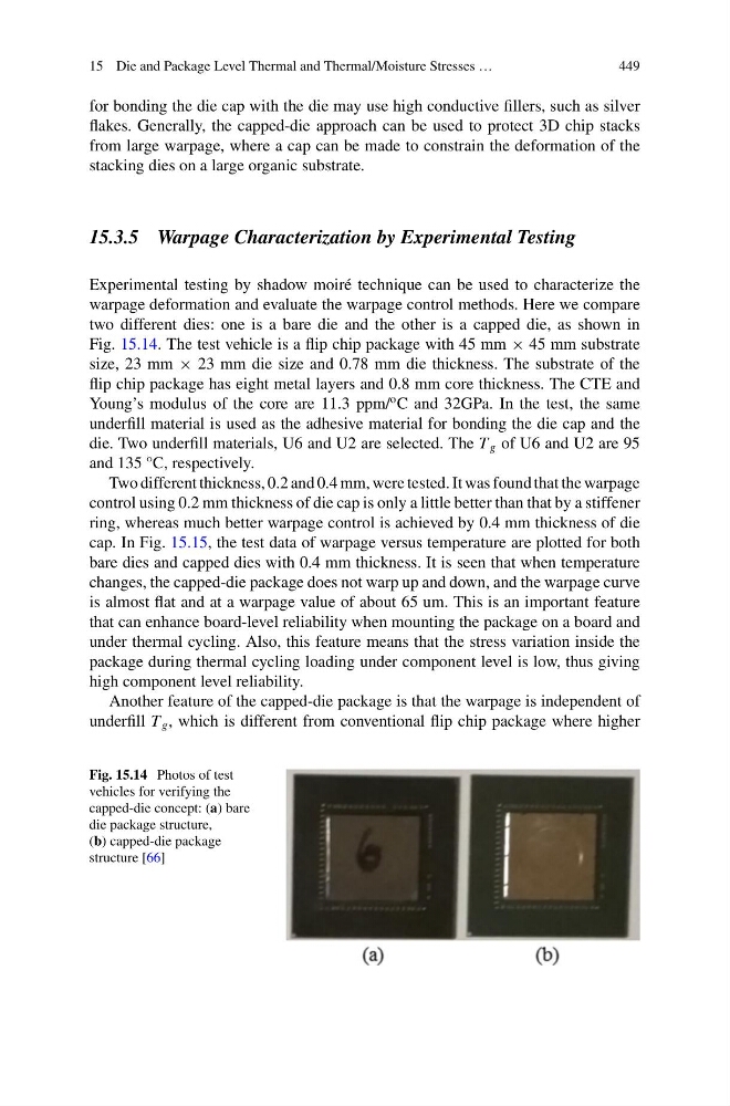
two different dies: one is a bare die and the other is a capped die, as shown in
Fig. 15.14. The test vehicle is a flip chip package with 45 mm × 45 mm substrate
size, 23 mm × 23 mm die size and 0.78 mm die thickness. The substrate of the
flip chip package has eight metal layers and 0.8 mm core thickness. The CTE and
Young’s modulus of the core are 11.3 ppm/
o C and 32GPa. In the test, the same
underfill material is used as the adhesive material for bonding the die cap and the
die. Two underfill materials, U6 and U2 are selected. The T g of U6 and U2 are 95
and 135 °C, respectively.
Two different thickness, 0.2 and 0.4 mm, were tested. It was found that the warpage
control using 0.2 mm thickness of die cap is only a little better than that by a stiffener
ring, whereas much better warpage control is achieved by 0.4 mm thickness of die
cap. In Fig. 15.15, the test data of warpage versus temperature are plotted for both
bare dies and capped dies with 0.4 mm thickness. It is seen that when temperature
changes, the capped-die package does not warp up and down, and the warpage curve
is almost flat and at a warpage value of about 65 um. This is an important feature
that can enhance board-level reliability when mounting the package on a board and
under thermal cycling. Also, this feature means that the stress variation inside the
package during thermal cycling loading under component level is low, thus giving
high component level reliability.
Another feature of the capped-die package is that the warpage is independent of
underfill T g , which is different from conventional flip chip package where higher
Fig. 15.14 Photos of test
vehicles for verifying the
capped-die concept: (a) bare
die package structure,
(b) capped-die package
structure [66]
449
for bonding the die cap with the die may use high conductive fillers, such as silver
flakes. Generally, the capped-die approach can be used to protect 3D chip stacks
from large warpage, where a cap can be made to constrain the deformation of the
stacking dies on a large organic substrate.
15.3.5 Warpage Characterization by Experimental Testing
Experimental testing by shadow moiré technique can be used to characterize the
warpage deformation and evaluate the warpage control methods. Here we compare
two different dies: one is a bare die and the other is a capped die, as shown in
Fig. 15.14. The test vehicle is a flip chip package with 45 mm × 45 mm substrate
size, 23 mm × 23 mm die size and 0.78 mm die thickness. The substrate of the
flip chip package has eight metal layers and 0.8 mm core thickness. The CTE and
Young’s modulus of the core are 11.3 ppm/
o C and 32GPa. In the test, the same
underfill material is used as the adhesive material for bonding the die cap and the
die. Two underfill materials, U6 and U2 are selected. The T g of U6 and U2 are 95
and 135 °C, respectively.
Two different thickness, 0.2 and 0.4 mm, were tested. It was found that the warpage
control using 0.2 mm thickness of die cap is only a little better than that by a stiffener
ring, whereas much better warpage control is achieved by 0.4 mm thickness of die
cap. In Fig. 15.15, the test data of warpage versus temperature are plotted for both
bare dies and capped dies with 0.4 mm thickness. It is seen that when temperature
changes, the capped-die package does not warp up and down, and the warpage curve
is almost flat and at a warpage value of about 65 um. This is an important feature
that can enhance board-level reliability when mounting the package on a board and
under thermal cycling. Also, this feature means that the stress variation inside the
package during thermal cycling loading under component level is low, thus giving
high component level reliability.
Another feature of the capped-die package is that the warpage is independent of
underfill T g , which is different from conventional flip chip package where higher
Fig. 15.14 Photos of test
vehicles for verifying the
capped-die concept: (a) bare
die package structure,
(b) capped-die package
structure [66]