

448
L. Chen et al.
15.3.4 A Capped-Die Approach for Warpage Control
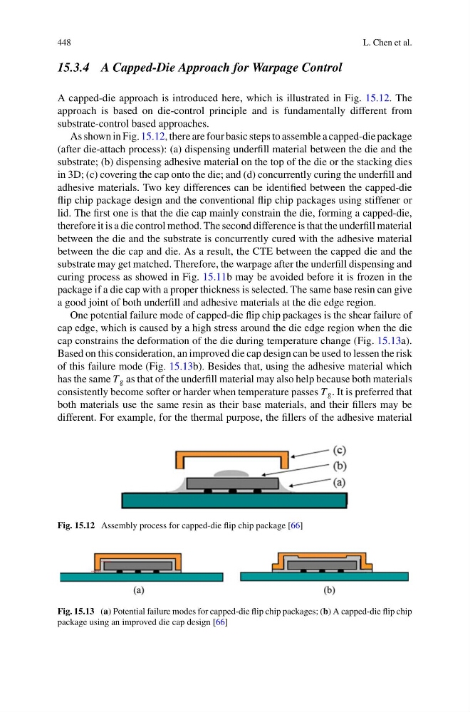
A capped-die approach is introduced here, which is illustrated in Fig. 15.12. The
approach is based on die-control principle and is fundamentally different from
substrate-control based approaches.
As shown in Fig. 15.12, there are four basic steps to assemble a capped-die package
(after die-attach process): (a) dispensing underfill material between the die and the
substrate; (b) dispensing adhesive material on the top of the die or the stacking dies
in 3D; (c) covering the cap onto the die; and (d) concurrently curing the underfill and
adhesive materials. Two key differences can be identified between the capped-die
flip chip package design and the conventional flip chip packages using stiffener or
lid. The first one is that the die cap mainly constrain the die, forming a capped-die,
therefore it is a die control method. The second difference is that the underfill material
between the die and the substrate is concurrently cured with the adhesive material
between the die cap and die. As a result, the CTE between the capped die and the
substrate may get matched. Therefore, the warpage after the underfill dispensing and
curing process as showed in Fig. 15.11b may be avoided before it is frozen in the
package if a die cap with a proper thickness is selected. The same base resin can give
a good joint of both underfill and adhesive materials at the die edge region.
One potential failure mode of capped-die flip chip packages is the shear failure of
cap edge, which is caused by a high stress around the die edge region when the die
cap constrains the deformation of the die during temperature change (Fig. 15.13a).
Based on this consideration, an improved die cap design can be used to lessen the risk
of this failure mode (Fig. 15.13b). Besides that, using the adhesive material which
has the same T g as that of the underfill material may also help because both materials
consistently become softer or harder when temperature passes T g . It is preferred that
both materials use the same resin as their base materials, and their fillers may be
different. For example, for the thermal purpose, the fillers of the adhesive material
Fig. 15.12 Assembly process for capped-die flip chip package [66]
Fig. 15.13 (a) Potential failure modes for capped-die flip chip packages; (b) A capped-die flip chip
package using an improved die cap design [66]
L. Chen et al.
15.3.4 A Capped-Die Approach for Warpage Control
A capped-die approach is introduced here, which is illustrated in Fig. 15.12. The
approach is based on die-control principle and is fundamentally different from
substrate-control based approaches.
As shown in Fig. 15.12, there are four basic steps to assemble a capped-die package
(after die-attach process): (a) dispensing underfill material between the die and the
substrate; (b) dispensing adhesive material on the top of the die or the stacking dies
in 3D; (c) covering the cap onto the die; and (d) concurrently curing the underfill and
adhesive materials. Two key differences can be identified between the capped-die
flip chip package design and the conventional flip chip packages using stiffener or
lid. The first one is that the die cap mainly constrain the die, forming a capped-die,
therefore it is a die control method. The second difference is that the underfill material
between the die and the substrate is concurrently cured with the adhesive material
between the die cap and die. As a result, the CTE between the capped die and the
substrate may get matched. Therefore, the warpage after the underfill dispensing and
curing process as showed in Fig. 15.11b may be avoided before it is frozen in the
package if a die cap with a proper thickness is selected. The same base resin can give
a good joint of both underfill and adhesive materials at the die edge region.
One potential failure mode of capped-die flip chip packages is the shear failure of
cap edge, which is caused by a high stress around the die edge region when the die
cap constrains the deformation of the die during temperature change (Fig. 15.13a).
Based on this consideration, an improved die cap design can be used to lessen the risk
of this failure mode (Fig. 15.13b). Besides that, using the adhesive material which
has the same T g as that of the underfill material may also help because both materials
consistently become softer or harder when temperature passes T g . It is preferred that
both materials use the same resin as their base materials, and their fillers may be
different. For example, for the thermal purpose, the fillers of the adhesive material
Fig. 15.12 Assembly process for capped-die flip chip package [66]
Fig. 15.13 (a) Potential failure modes for capped-die flip chip packages; (b) A capped-die flip chip
package using an improved die cap design [66]