

26
R. Mahajan and B. Sankman
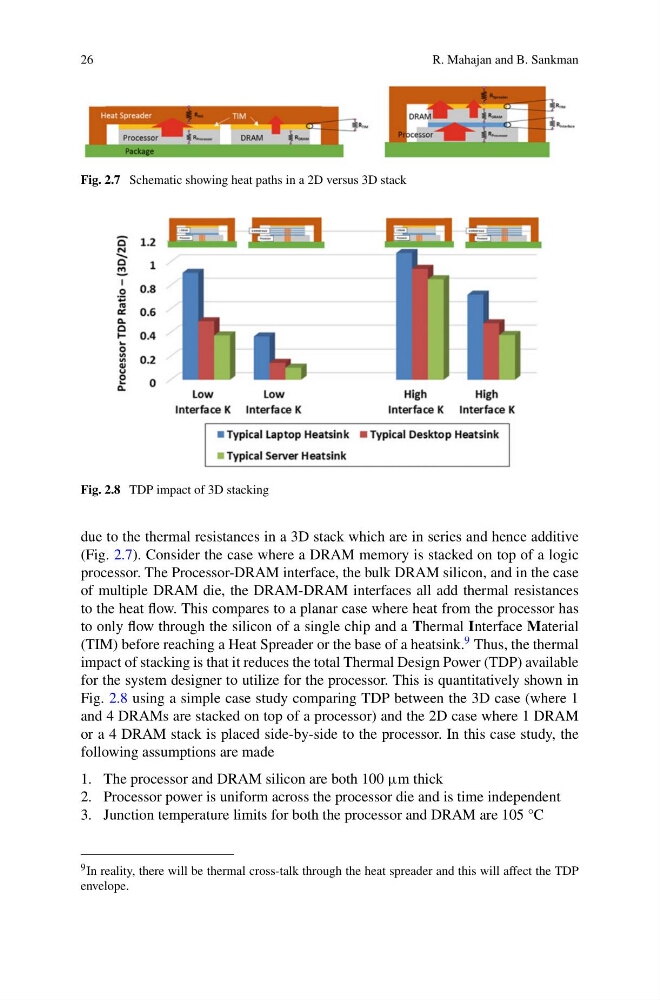
Fig. 2.7 Schematic showing heat paths in a 2D versus 3D stack
Fig. 2.8 TDP impact of 3D stacking
due to the thermal resistances in a 3D stack which are in series and hence additive
(Fig. 2.7). Consider the case where a DRAM memory is stacked on top of a logic
processor. The Processor-DRAM interface, the bulk DRAM silicon, and in the case
of multiple DRAM die, the DRAM-DRAM interfaces all add thermal resistances
to the heat flow. This compares to a planar case where heat from the processor has
to only flow through the silicon of a single chip and a Thermal Interface Material
(TIM) before reaching a Heat Spreader or the base of a heatsink.
9 Thus, the thermal
impact of stacking is that it reduces the total Thermal Design Power (TDP) available
for the system designer to utilize for the processor. This is quantitatively shown in
Fig. 2.8 using a simple case study comparing TDP between the 3D case (where 1
and 4 DRAMs are stacked on top of a processor) and the 2D case where 1 DRAM
or a 4 DRAM stack is placed side-by-side to the processor. In this case study, the
following assumptions are made
1. The processor and DRAM silicon are both 100 µm thick
2. Processor power is uniform across the processor die and is time independent
3. Junction temperature limits for both the processor and DRAM are 105 °C
9 In reality, there will be thermal cross-talk through the heat spreader and this will affect the TDP
envelope.
R. Mahajan and B. Sankman
Fig. 2.7 Schematic showing heat paths in a 2D versus 3D stack
Fig. 2.8 TDP impact of 3D stacking
due to the thermal resistances in a 3D stack which are in series and hence additive
(Fig. 2.7). Consider the case where a DRAM memory is stacked on top of a logic
processor. The Processor-DRAM interface, the bulk DRAM silicon, and in the case
of multiple DRAM die, the DRAM-DRAM interfaces all add thermal resistances
to the heat flow. This compares to a planar case where heat from the processor has
to only flow through the silicon of a single chip and a Thermal Interface Material
(TIM) before reaching a Heat Spreader or the base of a heatsink.
9 Thus, the thermal
impact of stacking is that it reduces the total Thermal Design Power (TDP) available
for the system designer to utilize for the processor. This is quantitatively shown in
Fig. 2.8 using a simple case study comparing TDP between the 3D case (where 1
and 4 DRAMs are stacked on top of a processor) and the 2D case where 1 DRAM
or a 4 DRAM stack is placed side-by-side to the processor. In this case study, the
following assumptions are made
1. The processor and DRAM silicon are both 100 µm thick
2. Processor power is uniform across the processor die and is time independent
3. Junction temperature limits for both the processor and DRAM are 105 °C
9 In reality, there will be thermal cross-talk through the heat spreader and this will affect the TDP
envelope.