

13 Fundamentals of Heat Dissipation in 3D IC Packaging …
389
Fig. 13.10 Increasing the fin density in several discrete zones along the flow length. Redrawn from
[47]
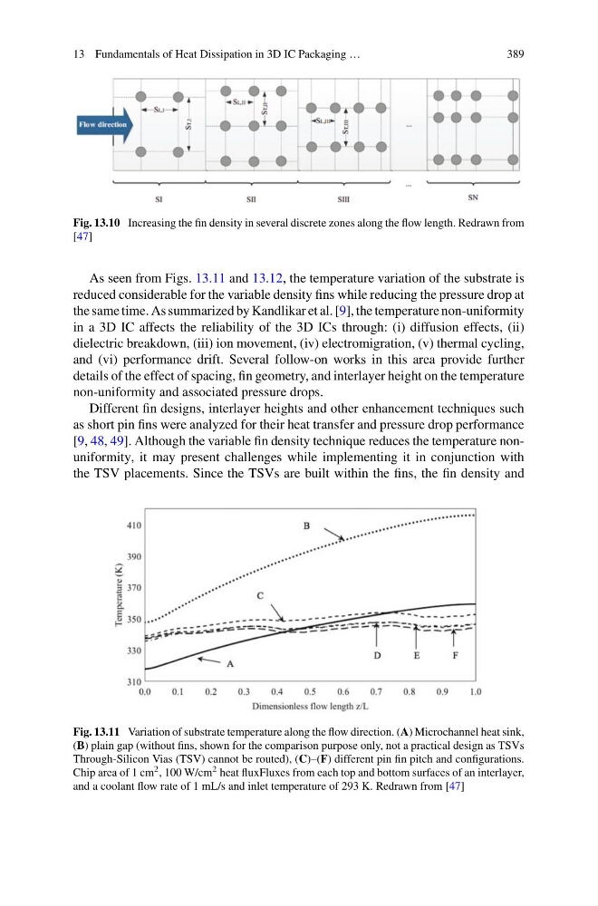
As seen from Figs. 13.11 and 13.12, the temperature variation of the substrate is
reduced considerable for the variable density fins while reducing the pressure drop at
the same time. As summarized by Kandlikar et al. [9], the temperature non-uniformity
in a 3D IC affects the reliability of the 3D ICs through: (i) diffusion effects, (ii)
dielectric breakdown, (iii) ion movement, (iv) electromigration, (v) thermal cycling,
and (vi) performance drift. Several follow-on works in this area provide further
details of the effect of spacing, fin geometry, and interlayer height on the temperature
non-uniformity and associated pressure drops.
Different fin designs, interlayer heights and other enhancement techniques such
as short pin fins were analyzed for their heat transfer and pressure drop performance
[9, 48, 49]. Although the variable fin density technique reduces the temperature nonuniformity, it may present challenges while implementing it in conjunction with
the TSV placements. Since the TSVs are built within the fins, the fin density and
Fig. 13.11 Variation of substrate temperature along the flow direction. (A) Microchannel heat sink,
(B) plain gap (without fins, shown for the comparison purpose only, not a practical design as TSVs
Through-Silicon Vias (TSV) cannot be routed), (C)–(F) different pin fin pitch and configurations.
Chip area of 1 cm 2 , 100 W/cm 2 heat fluxFluxes from each top and bottom surfaces of an interlayer,
and a coolant flow rate of 1 mL/s and inlet temperature of 293 K. Redrawn from [47]
389
Fig. 13.10 Increasing the fin density in several discrete zones along the flow length. Redrawn from
[47]
As seen from Figs. 13.11 and 13.12, the temperature variation of the substrate is
reduced considerable for the variable density fins while reducing the pressure drop at
the same time. As summarized by Kandlikar et al. [9], the temperature non-uniformity
in a 3D IC affects the reliability of the 3D ICs through: (i) diffusion effects, (ii)
dielectric breakdown, (iii) ion movement, (iv) electromigration, (v) thermal cycling,
and (vi) performance drift. Several follow-on works in this area provide further
details of the effect of spacing, fin geometry, and interlayer height on the temperature
non-uniformity and associated pressure drops.
Different fin designs, interlayer heights and other enhancement techniques such
as short pin fins were analyzed for their heat transfer and pressure drop performance
[9, 48, 49]. Although the variable fin density technique reduces the temperature nonuniformity, it may present challenges while implementing it in conjunction with
the TSV placements. Since the TSVs are built within the fins, the fin density and
Fig. 13.11 Variation of substrate temperature along the flow direction. (A) Microchannel heat sink,
(B) plain gap (without fins, shown for the comparison purpose only, not a practical design as TSVs
Through-Silicon Vias (TSV) cannot be routed), (C)–(F) different pin fin pitch and configurations.
Chip area of 1 cm 2 , 100 W/cm 2 heat fluxFluxes from each top and bottom surfaces of an interlayer,
and a coolant flow rate of 1 mL/s and inlet temperature of 293 K. Redrawn from [47]