

388
S. G. Kandlikar and A. Ganguly
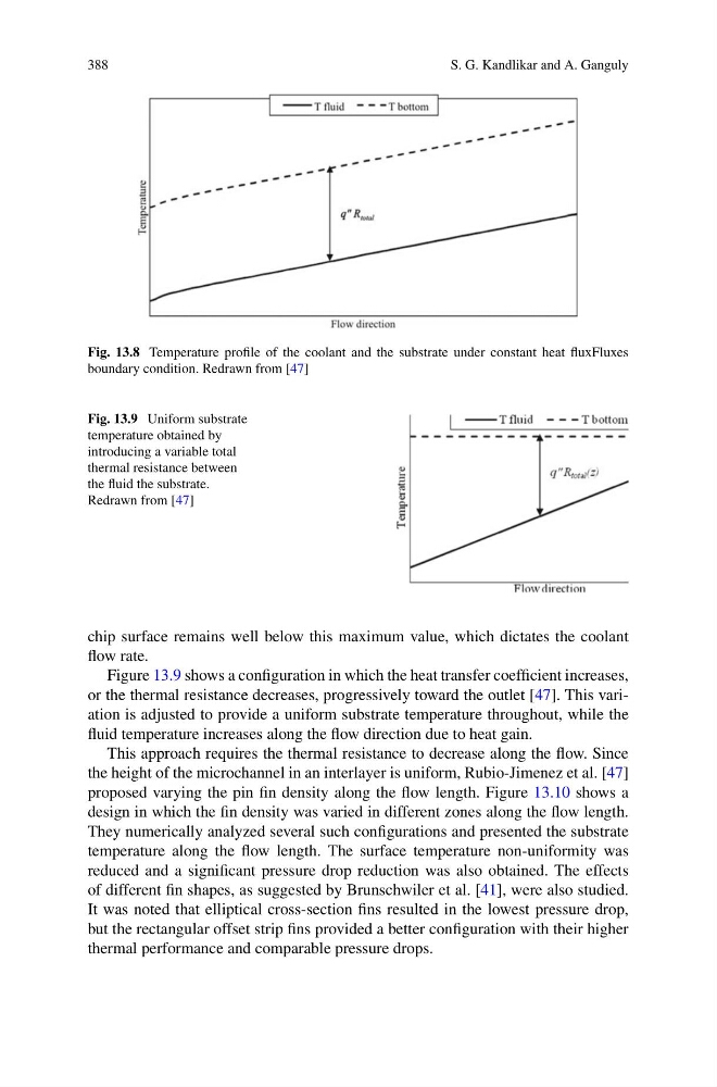
Fig. 13.8 Temperature profile of the coolant and the substrate under constant heat fluxFluxes
boundary condition. Redrawn from [47]
Fig. 13.9 Uniform substrate
temperature obtained by
introducing a variable total
thermal resistance between
the fluid the substrate.
Redrawn from [47]
chip surface remains well below this maximum value, which dictates the coolant
flow rate.
Figure 13.9 shows a configuration in which the heat transfer coefficient increases,
or the thermal resistance decreases, progressively toward the outlet [47]. This variation is adjusted to provide a uniform substrate temperature throughout, while the
fluid temperature increases along the flow direction due to heat gain.
This approach requires the thermal resistance to decrease along the flow. Since
the height of the microchannel in an interlayer is uniform, Rubio-Jimenez et al. [47]
proposed varying the pin fin density along the flow length. Figure 13.10 shows a
design in which the fin density was varied in different zones along the flow length.
They numerically analyzed several such configurations and presented the substrate
temperature along the flow length. The surface temperature non-uniformity was
reduced and a significant pressure drop reduction was also obtained. The effects
of different fin shapes, as suggested by Brunschwiler et al. [41], were also studied.
It was noted that elliptical cross-section fins resulted in the lowest pressure drop,
but the rectangular offset strip fins provided a better configuration with their higher
thermal performance and comparable pressure drops.
S. G. Kandlikar and A. Ganguly
Fig. 13.8 Temperature profile of the coolant and the substrate under constant heat fluxFluxes
boundary condition. Redrawn from [47]
Fig. 13.9 Uniform substrate
temperature obtained by
introducing a variable total
thermal resistance between
the fluid the substrate.
Redrawn from [47]
chip surface remains well below this maximum value, which dictates the coolant
flow rate.
Figure 13.9 shows a configuration in which the heat transfer coefficient increases,
or the thermal resistance decreases, progressively toward the outlet [47]. This variation is adjusted to provide a uniform substrate temperature throughout, while the
fluid temperature increases along the flow direction due to heat gain.
This approach requires the thermal resistance to decrease along the flow. Since
the height of the microchannel in an interlayer is uniform, Rubio-Jimenez et al. [47]
proposed varying the pin fin density along the flow length. Figure 13.10 shows a
design in which the fin density was varied in different zones along the flow length.
They numerically analyzed several such configurations and presented the substrate
temperature along the flow length. The surface temperature non-uniformity was
reduced and a significant pressure drop reduction was also obtained. The effects
of different fin shapes, as suggested by Brunschwiler et al. [41], were also studied.
It was noted that elliptical cross-section fins resulted in the lowest pressure drop,
but the rectangular offset strip fins provided a better configuration with their higher
thermal performance and comparable pressure drops.