

364
P. Liu
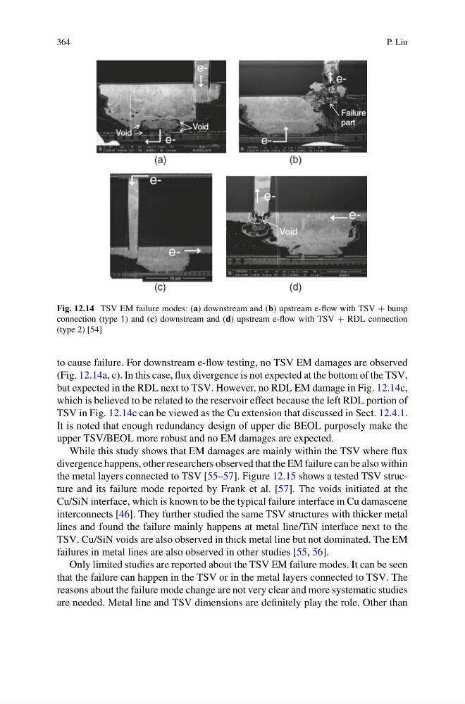
Fig. 12.14 TSV EM failure modes: (a) downstream and (b) upstream e-flow with TSV + bump
connection (type 1) and (c) downstream and (d) upstream e-flow with TSV + RDL connection
(type 2) [54]
to cause failure. For downstream e-flow testing, no TSV EM damages are observed
(Fig. 12.14a, c). In this case, flux divergence is not expected at the bottom of the TSV,
but expected in the RDL next to TSV. However, no RDL EM damage in Fig. 12.14c,
which is believed to be related to the reservoir effect because the left RDL portion of
TSV in Fig. 12.14c can be viewed as the Cu extension that discussed in Sect. 12.4.1.
It is noted that enough redundancy design of upper die BEOL purposely make the
upper TSV/BEOL more robust and no EM damages are expected.
While this study shows that EM damages are mainly within the TSV where flux
divergence happens, other researchers observed that the EM failure can be also within
the metal layers connected to TSV [55–57]. Figure 12.15 shows a tested TSV structure and its failure mode reported by Frank et al. [57]. The voids initiated at the
Cu/SiN interface, which is known to be the typical failure interface in Cu damascene
interconnects [46]. They further studied the same TSV structures with thicker metal
lines and found the failure mainly happens at metal line/TiN interface next to the
TSV. Cu/SiN voids are also observed in thick metal line but not dominated. The EM
failures in metal lines are also observed in other studies [55, 56].
Only limited studies are reported about the TSV EM failure modes. It can be seen
that the failure can happen in the TSV or in the metal layers connected to TSV. The
reasons about the failure mode change are not very clear and more systematic studies
are needed. Metal line and TSV dimensions are definitely play the role. Other than
P. Liu
Fig. 12.14 TSV EM failure modes: (a) downstream and (b) upstream e-flow with TSV + bump
connection (type 1) and (c) downstream and (d) upstream e-flow with TSV + RDL connection
(type 2) [54]
to cause failure. For downstream e-flow testing, no TSV EM damages are observed
(Fig. 12.14a, c). In this case, flux divergence is not expected at the bottom of the TSV,
but expected in the RDL next to TSV. However, no RDL EM damage in Fig. 12.14c,
which is believed to be related to the reservoir effect because the left RDL portion of
TSV in Fig. 12.14c can be viewed as the Cu extension that discussed in Sect. 12.4.1.
It is noted that enough redundancy design of upper die BEOL purposely make the
upper TSV/BEOL more robust and no EM damages are expected.
While this study shows that EM damages are mainly within the TSV where flux
divergence happens, other researchers observed that the EM failure can be also within
the metal layers connected to TSV [55–57]. Figure 12.15 shows a tested TSV structure and its failure mode reported by Frank et al. [57]. The voids initiated at the
Cu/SiN interface, which is known to be the typical failure interface in Cu damascene
interconnects [46]. They further studied the same TSV structures with thicker metal
lines and found the failure mainly happens at metal line/TiN interface next to the
TSV. Cu/SiN voids are also observed in thick metal line but not dominated. The EM
failures in metal lines are also observed in other studies [55, 56].
Only limited studies are reported about the TSV EM failure modes. It can be seen
that the failure can happen in the TSV or in the metal layers connected to TSV. The
reasons about the failure mode change are not very clear and more systematic studies
are needed. Metal line and TSV dimensions are definitely play the role. Other than