

298
S. Lee
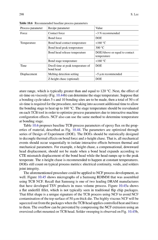
Table 10.6 Recommended baseline process parameters
Process parameter
Recipe parameter
Value
Force
Contact force
~3 N recommended
Bond force
DOE
Temperature
Bond head contact temperature
<160 °C
Bond head peak temperature
300 °C
Bond head release temperature
DOE/Above or equal to contact
temperature
Bond stage temperature
<160 °C
Time
Dwell time at peak temperature of
bond head
DOE
Displacement
Melting detection setting
~5 μm recommended
Z-height chase (optional)
DOE
ature range, which is typically greater than and equal to 120 °C. Next, the effect of
sit-time on viscosity (Fig. 10.44b) can determine the stage temperature. Suppose that
a bonding cycle takes 5 s and 10 bonding sites are to be made, then a total of 50 s of
sit-time is required for the procedure, not taking into account additional time to allow
the bonding stage to heat up to 160 °C. The stage temperature should be reevaluated
on each TCB tool in order to optimize process parameters due to interactive machine
configuration effects. NCF also can use the same method to determine temperature
at bonding stage.
Table 10.6 proposes baseline TCB process parameters of epoxy flux on the properties of material, described as Fig. 10.44. The parameters are optimized through
series of Design of Experiment (DOE). The DOEs should be statistically designed
to decouple thermal effects on bond force and z-height chase. That is, all mechanical
events should occur sequentially to isolate interactive effects between thermal and
mechanical parameters. For example, z-height chase, a compensational, downward
head displacement, should not be made when a bond head expands according to
CTE mismatch displacement of the bond head while the head ramps up to the peak
temperate. The z-height chase is recommended to happen at constant temperatures.
DOEs still count on typical process metrics: electrical continuity, voids, and solders
joint integrity.
The aforementioned procedure could be applied to NCF process development, as
well. Figure 10.45 shows micrographs of a Samsung RDIMM that was assembled
using TCB NCF. Recall that Samsung is one of two leading DRAM manufactures
that have developed TSV products in mass volume process. Figure 10.45a shows
a flat underfill fillet, which is not typically seen in traditional flip chip packages.
That fillet shape is a unique signature of the TCB process using NCF to avoid NCF
contamination of the top surface of 50 μm thick die. The highly viscous NCF will be
squeezed out from the packages when the TCB head applies controlled heat and force
to them. The overflow can be prevented by compressing the NCF extrusion using an
oversized collet mounted on TCB head. Solder sweeping is observed on Fig. 10.45b,
S. Lee
Table 10.6 Recommended baseline process parameters
Process parameter
Recipe parameter
Value
Force
Contact force
~3 N recommended
Bond force
DOE
Temperature
Bond head contact temperature
<160 °C
Bond head peak temperature
300 °C
Bond head release temperature
DOE/Above or equal to contact
temperature
Bond stage temperature
<160 °C
Time
Dwell time at peak temperature of
bond head
DOE
Displacement
Melting detection setting
~5 μm recommended
Z-height chase (optional)
DOE
ature range, which is typically greater than and equal to 120 °C. Next, the effect of
sit-time on viscosity (Fig. 10.44b) can determine the stage temperature. Suppose that
a bonding cycle takes 5 s and 10 bonding sites are to be made, then a total of 50 s of
sit-time is required for the procedure, not taking into account additional time to allow
the bonding stage to heat up to 160 °C. The stage temperature should be reevaluated
on each TCB tool in order to optimize process parameters due to interactive machine
configuration effects. NCF also can use the same method to determine temperature
at bonding stage.
Table 10.6 proposes baseline TCB process parameters of epoxy flux on the properties of material, described as Fig. 10.44. The parameters are optimized through
series of Design of Experiment (DOE). The DOEs should be statistically designed
to decouple thermal effects on bond force and z-height chase. That is, all mechanical
events should occur sequentially to isolate interactive effects between thermal and
mechanical parameters. For example, z-height chase, a compensational, downward
head displacement, should not be made when a bond head expands according to
CTE mismatch displacement of the bond head while the head ramps up to the peak
temperate. The z-height chase is recommended to happen at constant temperatures.
DOEs still count on typical process metrics: electrical continuity, voids, and solders
joint integrity.
The aforementioned procedure could be applied to NCF process development, as
well. Figure 10.45 shows micrographs of a Samsung RDIMM that was assembled
using TCB NCF. Recall that Samsung is one of two leading DRAM manufactures
that have developed TSV products in mass volume process. Figure 10.45a shows
a flat underfill fillet, which is not typically seen in traditional flip chip packages.
That fillet shape is a unique signature of the TCB process using NCF to avoid NCF
contamination of the top surface of 50 μm thick die. The highly viscous NCF will be
squeezed out from the packages when the TCB head applies controlled heat and force
to them. The overflow can be prevented by compressing the NCF extrusion using an
oversized collet mounted on TCB head. Solder sweeping is observed on Fig. 10.45b,