

10 Fundamentals of Bonding Technology and Process Materials …
297
Fig. 10.43 A schematic of solder bridge during stacking due to multiple times of solder reflow
As Fig. 10.42 indicates, TCB can utilize the epoxy flux or NCF for the stacking
process of fine pitch thin die having micro bumps and TSVs. Introduction of epoxy
flux technology will have technical challenges mostly in underfill process: (a)
precisely dispensing epoxy flux of less than 2 mg mass; (b) optimizing the process
sequence with respect to sit-time of material versus product throughput; and (c)
finding an epoxy flux material to meet a long sit-time requirement in TCB process.
Suppose that density of the epoxy is 1.6 cm/g
3 , the amount required is roughly 1.7 mg
to fill the gap height between die and bonding site (Table 10.5) [10]. Dispensing such
a small amount of epoxy flux with high repeatability and reproducibility, while not
causing underfill overflow on thin die, is an extremely difficult task when compared
to traditional underfill process for typical flip chip packages. Dispensing excessive
flux will also damage the TCB head, which is most important component in TCB
equipment. While the dispensing process must be optimized, fundamental investigations are also required to understand wetting and void formation of the material
candidates as well as validating long term reliability of the interconnecitons. Material
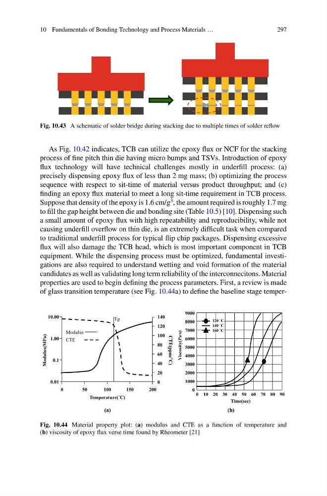
properties are used to begin defining the process parameters. First, a review is made
of glass transition temperature (see Fig. 10.44a) to define the baseline stage temper(a)
(b)
CTE
Modulus
Tg
50
100
150
200
10.00
1.00
0.1
0.01
120
100
80
40
20
0
60
140
0
Temperature(˚C)
CTE(ppm/˚C)
Modulus(MPa)
0
9 0
0
7
0
8
0
6
0
5
0
3
0
4
0
2
0
1
Time(sec)
1000
2000
3000
4000
5000
6000
7000
8000
9000
Viscosity(Pa∙s)
0
120 ˚C
140 ˚C
160 ˚C
Fig. 10.44 Material property plot: (a) modulus and CTE as a function of temperature and
(b) viscosity of epoxy flux verse time found by Rheometer [21]
297
Fig. 10.43 A schematic of solder bridge during stacking due to multiple times of solder reflow
As Fig. 10.42 indicates, TCB can utilize the epoxy flux or NCF for the stacking
process of fine pitch thin die having micro bumps and TSVs. Introduction of epoxy
flux technology will have technical challenges mostly in underfill process: (a)
precisely dispensing epoxy flux of less than 2 mg mass; (b) optimizing the process
sequence with respect to sit-time of material versus product throughput; and (c)
finding an epoxy flux material to meet a long sit-time requirement in TCB process.
Suppose that density of the epoxy is 1.6 cm/g
3 , the amount required is roughly 1.7 mg
to fill the gap height between die and bonding site (Table 10.5) [10]. Dispensing such
a small amount of epoxy flux with high repeatability and reproducibility, while not
causing underfill overflow on thin die, is an extremely difficult task when compared
to traditional underfill process for typical flip chip packages. Dispensing excessive
flux will also damage the TCB head, which is most important component in TCB
equipment. While the dispensing process must be optimized, fundamental investigations are also required to understand wetting and void formation of the material
candidates as well as validating long term reliability of the interconnecitons. Material
properties are used to begin defining the process parameters. First, a review is made
of glass transition temperature (see Fig. 10.44a) to define the baseline stage temper(a)
(b)
CTE
Modulus
Tg
50
100
150
200
10.00
1.00
0.1
0.01
120
100
80
40
20
0
60
140
0
Temperature(˚C)
CTE(ppm/˚C)
Modulus(MPa)
0
9 0
0
7
0
8
0
6
0
5
0
3
0
4
0
2
0
1
Time(sec)
1000
2000
3000
4000
5000
6000
7000
8000
9000
Viscosity(Pa∙s)
0
120 ˚C
140 ˚C
160 ˚C
Fig. 10.44 Material property plot: (a) modulus and CTE as a function of temperature and
(b) viscosity of epoxy flux verse time found by Rheometer [21]