

10 Fundamentals of Bonding Technology and Process Materials …
293
Epoxy Flux Dispensing
TCB
Post Curing(OpƟonal)
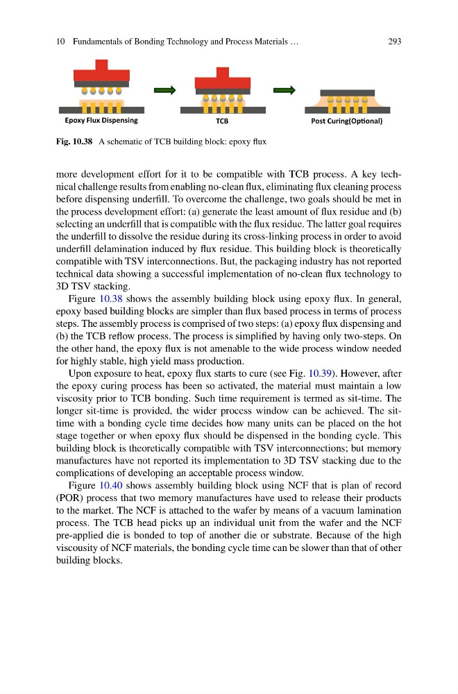
Fig. 10.38 A schematic of TCB building block: epoxy flux
more development effort for it to be compatible with TCB process. A key technical challenge results from enabling no-clean flux, eliminating flux cleaning process
before dispensing underfill. To overcome the challenge, two goals should be met in
the process development effort: (a) generate the least amount of flux residue and (b)
selecting an underfill that is compatible with the flux residue. The latter goal requires
the underfill to dissolve the residue during its cross-linking process in order to avoid
underfill delamination induced by flux residue. This building block is theoretically
compatible with TSV interconnections. But, the packaging industry has not reported
technical data showing a successful implementation of no-clean flux technology to
3D TSV stacking.
Figure 10.38 shows the assembly building block using epoxy flux. In general,
epoxy based building blocks are simpler than flux based process in terms of process
steps. The assembly process is comprised of two steps: (a) epoxy flux dispensing and
(b) the TCB reflow process. The process is simplified by having only two-steps. On
the other hand, the epoxy flux is not amenable to the wide process window needed
for highly stable, high yield mass production.
Upon exposure to heat, epoxy flux starts to cure (see Fig. 10.39). However, after
the epoxy curing process has been so activated, the material must maintain a low
viscosity prior to TCB bonding. Such time requirement is termed as sit-time. The
longer sit-time is provided, the wider process window can be achieved. The sittime with a bonding cycle time decides how many units can be placed on the hot
stage together or when epoxy flux should be dispensed in the bonding cycle. This
building block is theoretically compatible with TSV interconnections; but memory
manufactures have not reported its implementation to 3D TSV stacking due to the
complications of developing an acceptable process window.
Figure 10.40 shows assembly building block using NCF that is plan of record
(POR) process that two memory manufactures have used to release their products
to the market. The NCF is attached to the wafer by means of a vacuum lamination
process. The TCB head picks up an individual unit from the wafer and the NCF
pre-applied die is bonded to top of another die or substrate. Because of the high
viscousity of NCF materials, the bonding cycle time can be slower than that of other
building blocks.
293
Epoxy Flux Dispensing
TCB
Post Curing(OpƟonal)
Fig. 10.38 A schematic of TCB building block: epoxy flux
more development effort for it to be compatible with TCB process. A key technical challenge results from enabling no-clean flux, eliminating flux cleaning process
before dispensing underfill. To overcome the challenge, two goals should be met in
the process development effort: (a) generate the least amount of flux residue and (b)
selecting an underfill that is compatible with the flux residue. The latter goal requires
the underfill to dissolve the residue during its cross-linking process in order to avoid
underfill delamination induced by flux residue. This building block is theoretically
compatible with TSV interconnections. But, the packaging industry has not reported
technical data showing a successful implementation of no-clean flux technology to
3D TSV stacking.
Figure 10.38 shows the assembly building block using epoxy flux. In general,
epoxy based building blocks are simpler than flux based process in terms of process
steps. The assembly process is comprised of two steps: (a) epoxy flux dispensing and
(b) the TCB reflow process. The process is simplified by having only two-steps. On
the other hand, the epoxy flux is not amenable to the wide process window needed
for highly stable, high yield mass production.
Upon exposure to heat, epoxy flux starts to cure (see Fig. 10.39). However, after
the epoxy curing process has been so activated, the material must maintain a low
viscosity prior to TCB bonding. Such time requirement is termed as sit-time. The
longer sit-time is provided, the wider process window can be achieved. The sittime with a bonding cycle time decides how many units can be placed on the hot
stage together or when epoxy flux should be dispensed in the bonding cycle. This
building block is theoretically compatible with TSV interconnections; but memory
manufactures have not reported its implementation to 3D TSV stacking due to the
complications of developing an acceptable process window.
Figure 10.40 shows assembly building block using NCF that is plan of record
(POR) process that two memory manufactures have used to release their products
to the market. The NCF is attached to the wafer by means of a vacuum lamination
process. The TCB head picks up an individual unit from the wafer and the NCF
pre-applied die is bonded to top of another die or substrate. Because of the high
viscousity of NCF materials, the bonding cycle time can be slower than that of other
building blocks.