

7 Fundamentals and Failures in Die Preparation for 3D Packaging
187
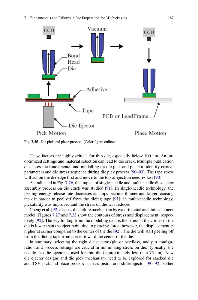
Fig. 7.25 Die pick and place process. (Color figure online)
These factors are highly critical for thin die, especially below 100 um. An unoptimized settings and material selection can lead to die crack. Multiple publication
discusses the fundamental and modelling on die pick and place to identify critical
parameters and die stress sequence during die pick process [90–93]. The tape stress
will act on the die edge first and move to the top of ejection needles last [90].
As indicated in Fig. 7.26, the impact of single-needle and multi-needle die ejector
assembly process on die crack was studied [91]. In single-needle technology, the
peeling energy release rate decreases as chips become thinner and larger, causing
the die harder to peel off from the dicing tape [91]; in multi-needle technology,
pickability was improved and the stress on die was reduced.
Cheng et al. [92] discuss die failure mechanism by experimental and finite element
model. Figures 7.27 and 7.28 show the contours of stress and displacement, respectively [92]. The key finding from the modeling data is the stress at the corner of the
die is lower than the eject point due to piercing force; however, the displacement is
higher at corner compared to the center of the die [92]. The die will start peeling off
from the dicing tape from corner toward the center of the die.
In summary, selecting the right die ejector (pin or needless) and pin configuration and process settings are crucial in minimizing stress on die. Typically, the
needle-less die ejector is used for thin die (approximately less than 75 um). New
die ejector designs and die pick mechanism need to be explored for stacked die
and TSV pick-and-place process such as piston and slider ejector [90–92]. Other
187
Fig. 7.25 Die pick and place process. (Color figure online)
These factors are highly critical for thin die, especially below 100 um. An unoptimized settings and material selection can lead to die crack. Multiple publication
discusses the fundamental and modelling on die pick and place to identify critical
parameters and die stress sequence during die pick process [90–93]. The tape stress
will act on the die edge first and move to the top of ejection needles last [90].
As indicated in Fig. 7.26, the impact of single-needle and multi-needle die ejector
assembly process on die crack was studied [91]. In single-needle technology, the
peeling energy release rate decreases as chips become thinner and larger, causing
the die harder to peel off from the dicing tape [91]; in multi-needle technology,
pickability was improved and the stress on die was reduced.
Cheng et al. [92] discuss die failure mechanism by experimental and finite element
model. Figures 7.27 and 7.28 show the contours of stress and displacement, respectively [92]. The key finding from the modeling data is the stress at the corner of the
die is lower than the eject point due to piercing force; however, the displacement is
higher at corner compared to the center of the die [92]. The die will start peeling off
from the dicing tape from corner toward the center of the die.
In summary, selecting the right die ejector (pin or needless) and pin configuration and process settings are crucial in minimizing stress on die. Typically, the
needle-less die ejector is used for thin die (approximately less than 75 um). New
die ejector designs and die pick mechanism need to be explored for stacked die
and TSV pick-and-place process such as piston and slider ejector [90–92]. Other