

186
H. Ma et al.
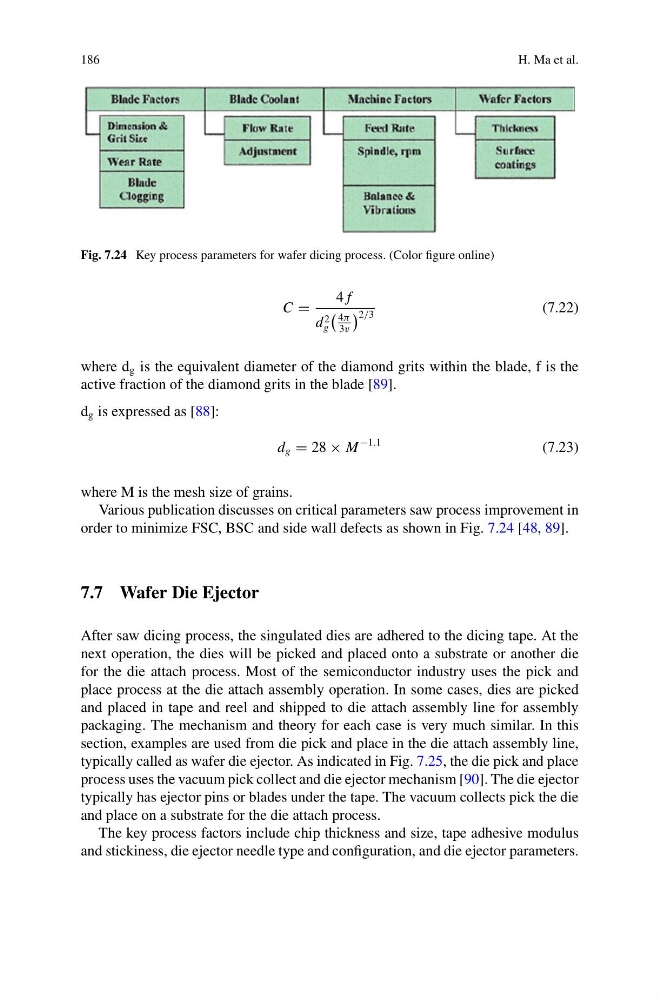
Fig. 7.24 Key process parameters for wafer dicing process. (Color figure online)
C =
4 f
d 2
g
4π
3v
2/3
(7.22)
where d g is the equivalent diameter of the diamond grits within the blade, f is the
active fraction of the diamond grits in the blade [89].
d g is expressed as [88]:
d g = 28 × M
−1.1
(7.23)
where M is the mesh size of grains.
Various publication discusses on critical parameters saw process improvement in
order to minimize FSC, BSC and side wall defects as shown in Fig. 7.24 [48, 89].
7.7 Wafer Die Ejector
After saw dicing process, the singulated dies are adhered to the dicing tape. At the
next operation, the dies will be picked and placed onto a substrate or another die
for the die attach process. Most of the semiconductor industry uses the pick and
place process at the die attach assembly operation. In some cases, dies are picked
and placed in tape and reel and shipped to die attach assembly line for assembly
packaging. The mechanism and theory for each case is very much similar. In this
section, examples are used from die pick and place in the die attach assembly line,
typically called as wafer die ejector. As indicated in Fig. 7.25, the die pick and place
process uses the vacuum pick collect and die ejector mechanism [90]. The die ejector
typically has ejector pins or blades under the tape. The vacuum collects pick the die
and place on a substrate for the die attach process.
The key process factors include chip thickness and size, tape adhesive modulus
and stickiness, die ejector needle type and configuration, and die ejector parameters.
H. Ma et al.
Fig. 7.24 Key process parameters for wafer dicing process. (Color figure online)
C =
4 f
d 2
g
4π
3v
2/3
(7.22)
where d g is the equivalent diameter of the diamond grits within the blade, f is the
active fraction of the diamond grits in the blade [89].
d g is expressed as [88]:
d g = 28 × M
−1.1
(7.23)
where M is the mesh size of grains.
Various publication discusses on critical parameters saw process improvement in
order to minimize FSC, BSC and side wall defects as shown in Fig. 7.24 [48, 89].
7.7 Wafer Die Ejector
After saw dicing process, the singulated dies are adhered to the dicing tape. At the
next operation, the dies will be picked and placed onto a substrate or another die
for the die attach process. Most of the semiconductor industry uses the pick and
place process at the die attach assembly operation. In some cases, dies are picked
and placed in tape and reel and shipped to die attach assembly line for assembly
packaging. The mechanism and theory for each case is very much similar. In this
section, examples are used from die pick and place in the die attach assembly line,
typically called as wafer die ejector. As indicated in Fig. 7.25, the die pick and place
process uses the vacuum pick collect and die ejector mechanism [90]. The die ejector
typically has ejector pins or blades under the tape. The vacuum collects pick the die
and place on a substrate for the die attach process.
The key process factors include chip thickness and size, tape adhesive modulus
and stickiness, die ejector needle type and configuration, and die ejector parameters.