

172
H. Ma et al.
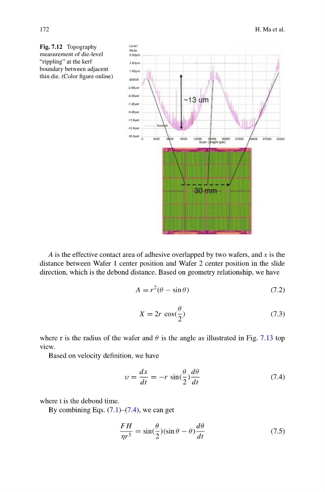
Fig. 7.12 Topography
measurement of die-level
“rippling” at the kerf
boundary between adjacent
thin die. (Color figure online)
A is the effective contact area of adhesive overlapped by two wafers, and x is the
distance between Wafer 1 center position and Wafer 2 center position in the slide
direction, which is the debond distance. Based on geometry relationship, we have
A = r
2
(θ − sin θ)
(7.2)
X = 2r cos(
θ
2
)
(7.3)
where r is the radius of the wafer and θ is the angle as illustrated in Fig. 7.13 top
view.
Based on velocity definition, we have
υ =
dx
dt
= −r sin(
θ
2
)
dθ
dt
(7.4)
where t is the debond time.
By combining Eqs. (7.1)–(7.4), we can get
F H
ηr 3 = sin(
θ
2
)(sin θ − θ)
dθ
dt
(7.5)
H. Ma et al.
Fig. 7.12 Topography
measurement of die-level
“rippling” at the kerf
boundary between adjacent
thin die. (Color figure online)
A is the effective contact area of adhesive overlapped by two wafers, and x is the
distance between Wafer 1 center position and Wafer 2 center position in the slide
direction, which is the debond distance. Based on geometry relationship, we have
A = r
2
(θ − sin θ)
(7.2)
X = 2r cos(
θ
2
)
(7.3)
where r is the radius of the wafer and θ is the angle as illustrated in Fig. 7.13 top
view.
Based on velocity definition, we have
υ =
dx
dt
= −r sin(
θ
2
)
dθ
dt
(7.4)
where t is the debond time.
By combining Eqs. (7.1)–(7.4), we can get
F H
ηr 3 = sin(
θ
2
)(sin θ − θ)
dθ
dt
(7.5)