

544
Z. Shao et al.
48.2 Instrument and Test Procedure
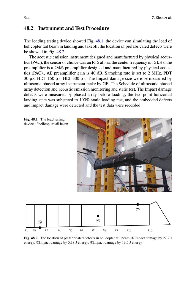
The loading testing device showed Fig. 48.1, the device can simulating the load of
helicopter tail beam in landing and takeoff, the location of prefabricated defects were
be showed in Fig. 48.2.
The acoustic emission instrument designed and manufactured by physical acoustics (PAC), the sensor of choice was an R15 alpha, the center frequency is 15 kHz, the
preamplifier is a 2/4/6 preamplifier designed and manufactured by physical acoustics (PAC)., AE preamplifier gain is 40 dB, Sampling rate is set to 2 MHz, PDT
30 µs, HDT 150 µs, HLT 300 µs. The Impact damage size were be measured by
ultrasonic phased array instrument make by GE. The Schedule of ultrasonic phased
array detection and acoustic emission monitoring and static test, The Impact damage
defects were measured by phased array before loading, the two-point horizontal
landing state was subjected to 100% static loading test, and the embedded defects
and impact damage were detected and the test data were recorded.
Fig. 48.1 The load testing
device of helicopter tail beam
Fig. 48.2 The location of prefabricated defects in helicopter tail beam: ➄Impact damage by 22.2 J
energy; ➅Impact damage by 5.18 J energy; ➆Impact damage by 13.5 J energy
Z. Shao et al.
48.2 Instrument and Test Procedure
The loading testing device showed Fig. 48.1, the device can simulating the load of
helicopter tail beam in landing and takeoff, the location of prefabricated defects were
be showed in Fig. 48.2.
The acoustic emission instrument designed and manufactured by physical acoustics (PAC), the sensor of choice was an R15 alpha, the center frequency is 15 kHz, the
preamplifier is a 2/4/6 preamplifier designed and manufactured by physical acoustics (PAC)., AE preamplifier gain is 40 dB, Sampling rate is set to 2 MHz, PDT
30 µs, HDT 150 µs, HLT 300 µs. The Impact damage size were be measured by
ultrasonic phased array instrument make by GE. The Schedule of ultrasonic phased
array detection and acoustic emission monitoring and static test, The Impact damage
defects were measured by phased array before loading, the two-point horizontal
landing state was subjected to 100% static loading test, and the embedded defects
and impact damage were detected and the test data were recorded.
Fig. 48.1 The load testing
device of helicopter tail beam
Fig. 48.2 The location of prefabricated defects in helicopter tail beam: ➄Impact damage by 22.2 J
energy; ➅Impact damage by 5.18 J energy; ➆Impact damage by 13.5 J energy