

47 Bearing Fault Transfer Diagnosis Based on Acoustic Emission …
539
Bearing 1
Bearing 2
Bearing 3
Radial Load
Acoustic emission sensor
Motor
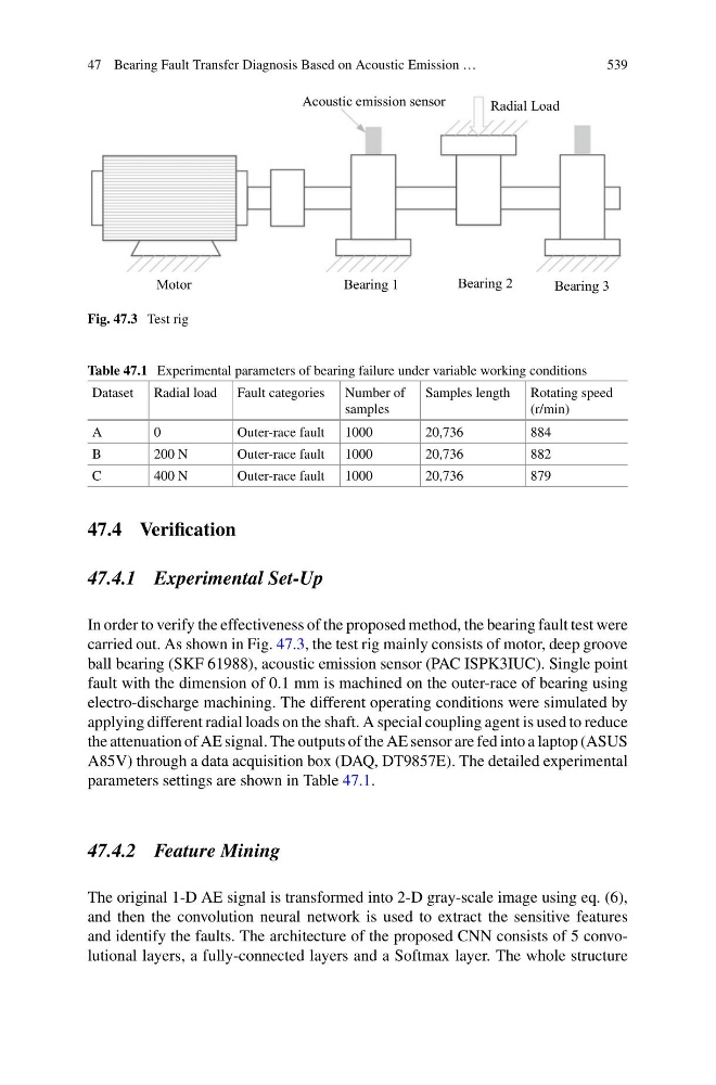
Fig. 47.3 Test rig
Table 47.1 Experimental parameters of bearing failure under variable working conditions
Dataset Radial load Fault categories Number of
samples
Samples length Rotating speed
(r/min)
A
0
Outer-race fault 1000
20,736
884
B
200 N
Outer-race fault 1000
20,736
882
C
400 N
Outer-race fault 1000
20,736
879
47.4 Verification
47.4.1 Experimental Set-Up
In order to verify the effectiveness of the proposed method, the bearing fault test were
carried out. As shown in Fig. 47.3, the test rig mainly consists of motor, deep groove
ball bearing (SKF 61988), acoustic emission sensor (PAC ISPK3IUC). Single point
fault with the dimension of 0.1 mm is machined on the outer-race of bearing using
electro-discharge machining. The different operating conditions were simulated by
applying different radial loads on the shaft. A special coupling agent is used to reduce
the attenuation of AE signal. The outputs of the AE sensor are fed into a laptop (ASUS
A85V) through a data acquisition box (DAQ, DT9857E). The detailed experimental
parameters settings are shown in Table 47.1.
47.4.2 Feature Mining
The original 1-D AE signal is transformed into 2-D gray-scale image using eq. (6),
and then the convolution neural network is used to extract the sensitive features
and identify the faults. The architecture of the proposed CNN consists of 5 convolutional layers, a fully-connected layers and a Softmax layer. The whole structure
539
Bearing 1
Bearing 2
Bearing 3
Radial Load
Acoustic emission sensor
Motor
Fig. 47.3 Test rig
Table 47.1 Experimental parameters of bearing failure under variable working conditions
Dataset Radial load Fault categories Number of
samples
Samples length Rotating speed
(r/min)
A
0
Outer-race fault 1000
20,736
884
B
200 N
Outer-race fault 1000
20,736
882
C
400 N
Outer-race fault 1000
20,736
879
47.4 Verification
47.4.1 Experimental Set-Up
In order to verify the effectiveness of the proposed method, the bearing fault test were
carried out. As shown in Fig. 47.3, the test rig mainly consists of motor, deep groove
ball bearing (SKF 61988), acoustic emission sensor (PAC ISPK3IUC). Single point
fault with the dimension of 0.1 mm is machined on the outer-race of bearing using
electro-discharge machining. The different operating conditions were simulated by
applying different radial loads on the shaft. A special coupling agent is used to reduce
the attenuation of AE signal. The outputs of the AE sensor are fed into a laptop (ASUS
A85V) through a data acquisition box (DAQ, DT9857E). The detailed experimental
parameters settings are shown in Table 47.1.
47.4.2 Feature Mining
The original 1-D AE signal is transformed into 2-D gray-scale image using eq. (6),
and then the convolution neural network is used to extract the sensitive features
and identify the faults. The architecture of the proposed CNN consists of 5 convolutional layers, a fully-connected layers and a Softmax layer. The whole structure