

468
F. Zohora et al.
41.3 Numerical and Experimental Test Set-Ups
41.3.1 Experimental Test Set-Up
The experimental set-up has two parts: test-rig and AE data acquisition equipment.
The pipe dimension was 1.2 m long and 125.4 mm inner diameter with 1.6 mm wall
thickness and the cylinder diameter was 25 mm. A flow meter and a pressure gauge
were used to measure the fluid flow rate and pressure at pipe outlet respectively.
A flow stabilized zone was introduced to the inlet of the pipe to make the fluid
stable before it passes over the cylinder. A higher flowrate was selected to generate
turbulent flow inside the pipe. Physical acoustic corporation (PAC) resonance sensor
(AE R15 α) with resonance frequency 150 kHz was mounted on the surface of
the pipe for capturing AE signals. The AE sensor was connected to a high-pass
(100 kHz) amplifier via a pre-amplifier. The gain of the amplifier and pre-amplifier
was 0 dB and 60 dB respectively. LabVIEW software was used for signal recording
through communication with NI 9223 module and MATLAB was used for signal
post-processing. The sampling frequency for data acquisition was selected manually
to 1 MHz for R15α.
41.3.2 Numerical Test Set-Up
A three-dimensional circular cylinder (as a bluff-body) inside a pipe was selected in
this study as a vortex generator to obtain vortex shedding frequency and lift force.
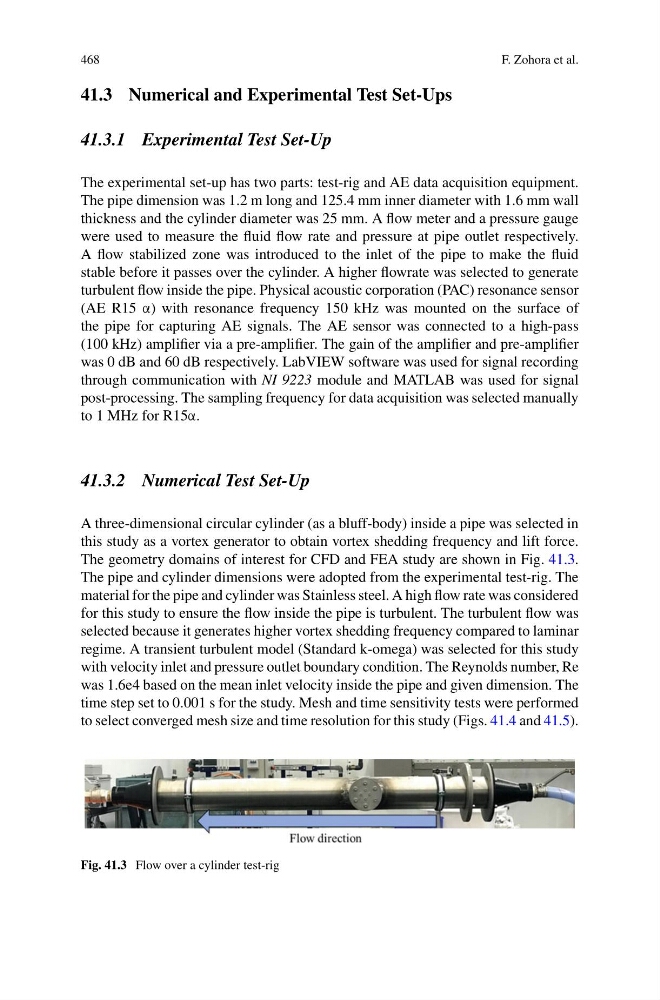
The geometry domains of interest for CFD and FEA study are shown in Fig. 41.3.
The pipe and cylinder dimensions were adopted from the experimental test-rig. The
material for the pipe and cylinder was Stainless steel. A high flow rate was considered
for this study to ensure the flow inside the pipe is turbulent. The turbulent flow was
selected because it generates higher vortex shedding frequency compared to laminar
regime. A transient turbulent model (Standard k-omega) was selected for this study
with velocity inlet and pressure outlet boundary condition. The Reynolds number, Re
was 1.6e4 based on the mean inlet velocity inside the pipe and given dimension. The
time step set to 0.001 s for the study. Mesh and time sensitivity tests were performed
to select converged mesh size and time resolution for this study (Figs. 41.4 and 41.5).
Fig. 41.3 Flow over a cylinder test-rig
F. Zohora et al.
41.3 Numerical and Experimental Test Set-Ups
41.3.1 Experimental Test Set-Up
The experimental set-up has two parts: test-rig and AE data acquisition equipment.
The pipe dimension was 1.2 m long and 125.4 mm inner diameter with 1.6 mm wall
thickness and the cylinder diameter was 25 mm. A flow meter and a pressure gauge
were used to measure the fluid flow rate and pressure at pipe outlet respectively.
A flow stabilized zone was introduced to the inlet of the pipe to make the fluid
stable before it passes over the cylinder. A higher flowrate was selected to generate
turbulent flow inside the pipe. Physical acoustic corporation (PAC) resonance sensor
(AE R15 α) with resonance frequency 150 kHz was mounted on the surface of
the pipe for capturing AE signals. The AE sensor was connected to a high-pass
(100 kHz) amplifier via a pre-amplifier. The gain of the amplifier and pre-amplifier
was 0 dB and 60 dB respectively. LabVIEW software was used for signal recording
through communication with NI 9223 module and MATLAB was used for signal
post-processing. The sampling frequency for data acquisition was selected manually
to 1 MHz for R15α.
41.3.2 Numerical Test Set-Up
A three-dimensional circular cylinder (as a bluff-body) inside a pipe was selected in
this study as a vortex generator to obtain vortex shedding frequency and lift force.
The geometry domains of interest for CFD and FEA study are shown in Fig. 41.3.
The pipe and cylinder dimensions were adopted from the experimental test-rig. The
material for the pipe and cylinder was Stainless steel. A high flow rate was considered
for this study to ensure the flow inside the pipe is turbulent. The turbulent flow was
selected because it generates higher vortex shedding frequency compared to laminar
regime. A transient turbulent model (Standard k-omega) was selected for this study
with velocity inlet and pressure outlet boundary condition. The Reynolds number, Re
was 1.6e4 based on the mean inlet velocity inside the pipe and given dimension. The
time step set to 0.001 s for the study. Mesh and time sensitivity tests were performed
to select converged mesh size and time resolution for this study (Figs. 41.4 and 41.5).
Fig. 41.3 Flow over a cylinder test-rig