

34 Application and Research of Acoustic Emission …
395
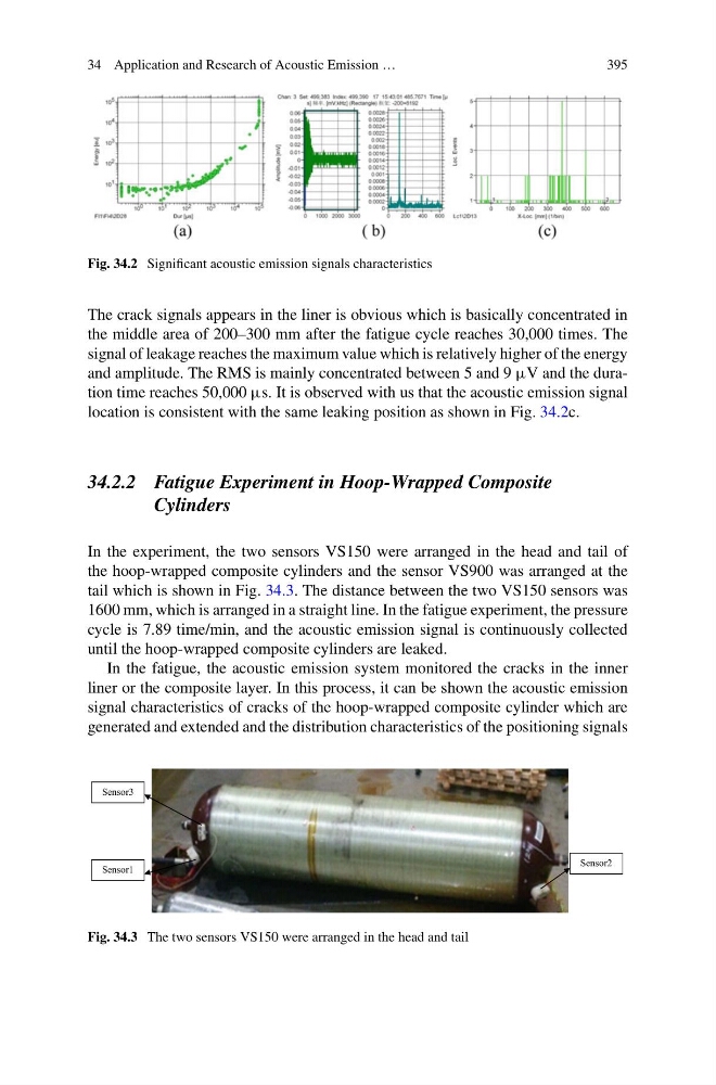
Fig. 34.2 Significant acoustic emission signals characteristics
The crack signals appears in the liner is obvious which is basically concentrated in
the middle area of 200–300 mm after the fatigue cycle reaches 30,000 times. The
signal of leakage reaches the maximum value which is relatively higher of the energy
and amplitude. The RMS is mainly concentrated between 5 and 9 µV and the duration time reaches 50,000 µs. It is observed with us that the acoustic emission signal
location is consistent with the same leaking position as shown in Fig. 34.2c.
34.2.2 Fatigue Experiment in Hoop-Wrapped Composite
Cylinders
In the experiment, the two sensors VS150 were arranged in the head and tail of
the hoop-wrapped composite cylinders and the sensor VS900 was arranged at the
tail which is shown in Fig. 34.3. The distance between the two VS150 sensors was
1600 mm, which is arranged in a straight line. In the fatigue experiment, the pressure
cycle is 7.89 time/min, and the acoustic emission signal is continuously collected
until the hoop-wrapped composite cylinders are leaked.
In the fatigue, the acoustic emission system monitored the cracks in the inner
liner or the composite layer. In this process, it can be shown the acoustic emission
signal characteristics of cracks of the hoop-wrapped composite cylinder which are
generated and extended and the distribution characteristics of the positioning signals
Sensor3
Sensor1
Sensor2
Fig. 34.3 The two sensors VS150 were arranged in the head and tail
395
Fig. 34.2 Significant acoustic emission signals characteristics
The crack signals appears in the liner is obvious which is basically concentrated in
the middle area of 200–300 mm after the fatigue cycle reaches 30,000 times. The
signal of leakage reaches the maximum value which is relatively higher of the energy
and amplitude. The RMS is mainly concentrated between 5 and 9 µV and the duration time reaches 50,000 µs. It is observed with us that the acoustic emission signal
location is consistent with the same leaking position as shown in Fig. 34.2c.
34.2.2 Fatigue Experiment in Hoop-Wrapped Composite
Cylinders
In the experiment, the two sensors VS150 were arranged in the head and tail of
the hoop-wrapped composite cylinders and the sensor VS900 was arranged at the
tail which is shown in Fig. 34.3. The distance between the two VS150 sensors was
1600 mm, which is arranged in a straight line. In the fatigue experiment, the pressure
cycle is 7.89 time/min, and the acoustic emission signal is continuously collected
until the hoop-wrapped composite cylinders are leaked.
In the fatigue, the acoustic emission system monitored the cracks in the inner
liner or the composite layer. In this process, it can be shown the acoustic emission
signal characteristics of cracks of the hoop-wrapped composite cylinder which are
generated and extended and the distribution characteristics of the positioning signals
Sensor3
Sensor1
Sensor2
Fig. 34.3 The two sensors VS150 were arranged in the head and tail