

380
Z. Hu et al.
In the formula, the calculation formula of L 1 and δ
,
3 is:
L 1 = x
2
2 + y
2
2 − δ
2
1 , L 2 = x
2
3 + y
2
3 − δ
2
2
(32.6)
δ
3 = r 3 −
(r 3 + δ 1 )
2
− z
2
1 , δ
2 = r 3 −
(r 3 + δ 2 )
2
− z
2
2
(32.7)
From this, the simultaneous equations can be solved to find r and θ in accordance
with the actual situation. The coordinates of acoustic emission sound source S at the
damaged part of the floor were obtained, and the damage location was completed.
32.3 Sensor Layout
According to the positioning principle, for small storage tanks. During acoustic
emission monitoring, in order to calculate the location of acoustic signals source
conveniently. The number of acoustic emission sensors should be at least 3. The
monitoring area is the triangular circumscribed circle of the three sensors on the
projection surface of the tank floor. In order to improve the accuracy of positioning,
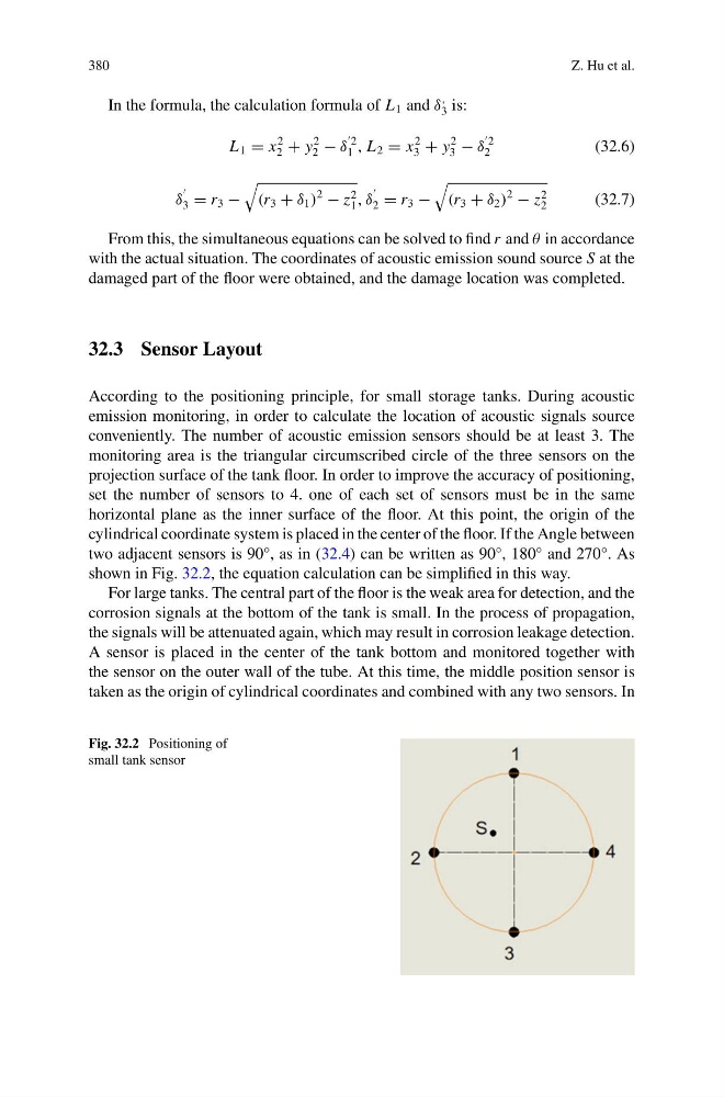
set the number of sensors to 4. one of each set of sensors must be in the same
horizontal plane as the inner surface of the floor. At this point, the origin of the
cylindrical coordinate system is placed in the center of the floor. If the Angle between
two adjacent sensors is 90°, as in (32.4) can be written as 90°, 180° and 270°. As
shown in Fig. 32.2, the equation calculation can be simplified in this way.
For large tanks. The central part of the floor is the weak area for detection, and the
corrosion signals at the bottom of the tank is small. In the process of propagation,
the signals will be attenuated again, which may result in corrosion leakage detection.
A sensor is placed in the center of the tank bottom and monitored together with
the sensor on the outer wall of the tube. At this time, the middle position sensor is
taken as the origin of cylindrical coordinates and combined with any two sensors. In
Fig. 32.2 Positioning of
small tank sensor
Z. Hu et al.
In the formula, the calculation formula of L 1 and δ
,
3 is:
L 1 = x
2
2 + y
2
2 − δ
2
1 , L 2 = x
2
3 + y
2
3 − δ
2
2
(32.6)
δ
3 = r 3 −
(r 3 + δ 1 )
2
− z
2
1 , δ
2 = r 3 −
(r 3 + δ 2 )
2
− z
2
2
(32.7)
From this, the simultaneous equations can be solved to find r and θ in accordance
with the actual situation. The coordinates of acoustic emission sound source S at the
damaged part of the floor were obtained, and the damage location was completed.
32.3 Sensor Layout
According to the positioning principle, for small storage tanks. During acoustic
emission monitoring, in order to calculate the location of acoustic signals source
conveniently. The number of acoustic emission sensors should be at least 3. The
monitoring area is the triangular circumscribed circle of the three sensors on the
projection surface of the tank floor. In order to improve the accuracy of positioning,
set the number of sensors to 4. one of each set of sensors must be in the same
horizontal plane as the inner surface of the floor. At this point, the origin of the
cylindrical coordinate system is placed in the center of the floor. If the Angle between
two adjacent sensors is 90°, as in (32.4) can be written as 90°, 180° and 270°. As
shown in Fig. 32.2, the equation calculation can be simplified in this way.
For large tanks. The central part of the floor is the weak area for detection, and the
corrosion signals at the bottom of the tank is small. In the process of propagation,
the signals will be attenuated again, which may result in corrosion leakage detection.
A sensor is placed in the center of the tank bottom and monitored together with
the sensor on the outer wall of the tube. At this time, the middle position sensor is
taken as the origin of cylindrical coordinates and combined with any two sensors. In
Fig. 32.2 Positioning of
small tank sensor