

32 Study on a Method of Corrosion Acoustic …
379
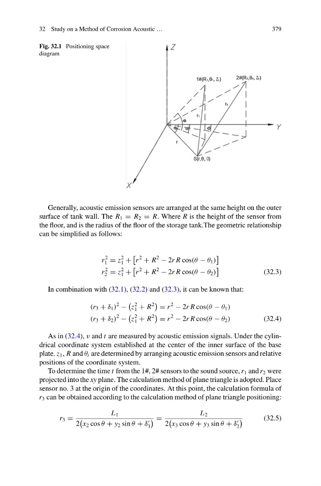
Fig. 32.1 Positioning space
diagram
Generally, acoustic emission sensors are arranged at the same height on the outer
surface of tank wall. The R 1 = R 2 = R. Where R is the height of the sensor from
the floor, and is the radius of the floor of the storage tank.The geometric relationship
can be simplified as follows:
r
2
1 = z
2
1 +
r
2
+ R
2
− 2r R cos(θ − θ 1 )
r
2
2 = z
2
1 +
r
2
+ R
2
− 2r R cos(θ − θ 2 )
(32.3)
In combination with (32.1), (32.2) and (32.3), it can be known that:
(r 3 + δ 1 )
2
−
z
2
1 + R
2
= r
2
− 2r R cos(θ − θ 1 )
(r 3 + δ 2 )
2
−
z
2
1 + R
2
= r
2
− 2r R cos(θ − θ 2 )
(32.4)
As in (32.4), v and t are measured by acoustic emission signals. Under the cylindrical coordinate system established at the center of the inner surface of the base
plate. z 1 , R and θ i are determined by arranging acoustic emission sensors and relative
positions of the coordinate system.
To determine the time t from the 1#, 2# sensors to the sound source, r 1 and r 2 were
projected into the xy plane. The calculation method of plane triangle is adopted. Place
sensor no. 3 at the origin of the coordinates. At this point, the calculation formula of
r 3 can be obtained according to the calculation method of plane triangle positioning:
r 3 =
L 1
2
x 2 cos θ + y 2 sin θ + δ
3
=
L 2
2
x 3 cos θ + y 3 sin θ + δ
2
(32.5)
379
Fig. 32.1 Positioning space
diagram
Generally, acoustic emission sensors are arranged at the same height on the outer
surface of tank wall. The R 1 = R 2 = R. Where R is the height of the sensor from
the floor, and is the radius of the floor of the storage tank.The geometric relationship
can be simplified as follows:
r
2
1 = z
2
1 +
r
2
+ R
2
− 2r R cos(θ − θ 1 )
r
2
2 = z
2
1 +
r
2
+ R
2
− 2r R cos(θ − θ 2 )
(32.3)
In combination with (32.1), (32.2) and (32.3), it can be known that:
(r 3 + δ 1 )
2
−
z
2
1 + R
2
= r
2
− 2r R cos(θ − θ 1 )
(r 3 + δ 2 )
2
−
z
2
1 + R
2
= r
2
− 2r R cos(θ − θ 2 )
(32.4)
As in (32.4), v and t are measured by acoustic emission signals. Under the cylindrical coordinate system established at the center of the inner surface of the base
plate. z 1 , R and θ i are determined by arranging acoustic emission sensors and relative
positions of the coordinate system.
To determine the time t from the 1#, 2# sensors to the sound source, r 1 and r 2 were
projected into the xy plane. The calculation method of plane triangle is adopted. Place
sensor no. 3 at the origin of the coordinates. At this point, the calculation formula of
r 3 can be obtained according to the calculation method of plane triangle positioning:
r 3 =
L 1
2
x 2 cos θ + y 2 sin θ + δ
3
=
L 2
2
x 3 cos θ + y 3 sin θ + δ
2
(32.5)