

32 Study on a Method of Corrosion Acoustic …
381
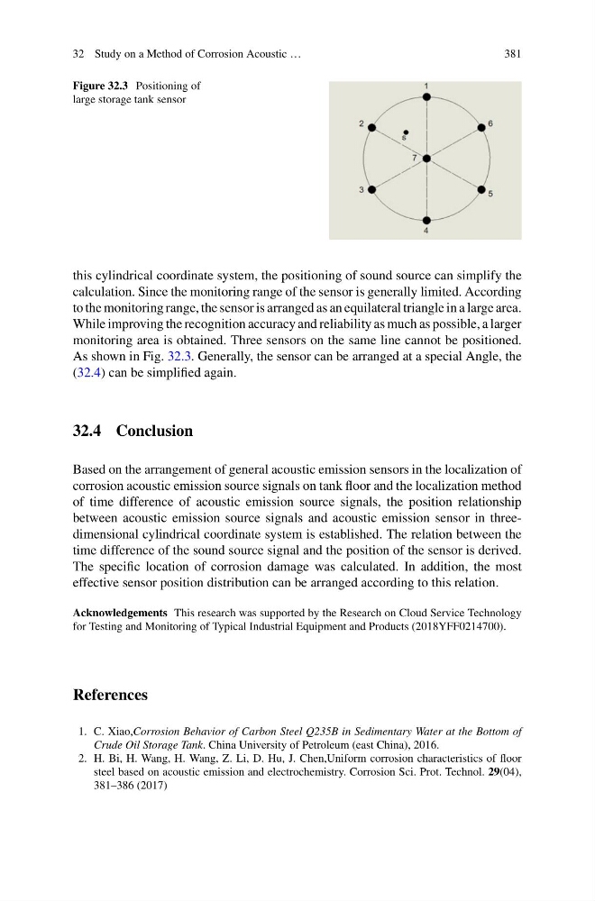
Figure 32.3 Positioning of
large storage tank sensor
this cylindrical coordinate system, the positioning of sound source can simplify the
calculation. Since the monitoring range of the sensor is generally limited. According
to the monitoring range, the sensor is arranged as an equilateral triangle in a large area.
While improving the recognition accuracy and reliability as much as possible, a larger
monitoring area is obtained. Three sensors on the same line cannot be positioned.
As shown in Fig. 32.3. Generally, the sensor can be arranged at a special Angle, the
(32.4) can be simplified again.
32.4 Conclusion
Based on the arrangement of general acoustic emission sensors in the localization of
corrosion acoustic emission source signals on tank floor and the localization method
of time difference of acoustic emission source signals, the position relationship
between acoustic emission source signals and acoustic emission sensor in threedimensional cylindrical coordinate system is established. The relation between the
time difference of the sound source signal and the position of the sensor is derived.
The specific location of corrosion damage was calculated. In addition, the most
effective sensor position distribution can be arranged according to this relation.
Acknowledgements This research was supported by the Research on Cloud Service Technology
for Testing and Monitoring of Typical Industrial Equipment and Products (2018YFF0214700).
References
1. C. Xiao,Corrosion Behavior of Carbon Steel Q235B in Sedimentary Water at the Bottom of
Crude Oil Storage Tank. China University of Petroleum (east China), 2016.
2. H. Bi, H. Wang, H. Wang, Z. Li, D. Hu, J. Chen,Uniform corrosion characteristics of floor
steel based on acoustic emission and electrochemistry. Corrosion Sci. Prot. Technol. 29(04),
381–386 (2017)
381
Figure 32.3 Positioning of
large storage tank sensor
this cylindrical coordinate system, the positioning of sound source can simplify the
calculation. Since the monitoring range of the sensor is generally limited. According
to the monitoring range, the sensor is arranged as an equilateral triangle in a large area.
While improving the recognition accuracy and reliability as much as possible, a larger
monitoring area is obtained. Three sensors on the same line cannot be positioned.
As shown in Fig. 32.3. Generally, the sensor can be arranged at a special Angle, the
(32.4) can be simplified again.
32.4 Conclusion
Based on the arrangement of general acoustic emission sensors in the localization of
corrosion acoustic emission source signals on tank floor and the localization method
of time difference of acoustic emission source signals, the position relationship
between acoustic emission source signals and acoustic emission sensor in threedimensional cylindrical coordinate system is established. The relation between the
time difference of the sound source signal and the position of the sensor is derived.
The specific location of corrosion damage was calculated. In addition, the most
effective sensor position distribution can be arranged according to this relation.
Acknowledgements This research was supported by the Research on Cloud Service Technology
for Testing and Monitoring of Typical Industrial Equipment and Products (2018YFF0214700).
References
1. C. Xiao,Corrosion Behavior of Carbon Steel Q235B in Sedimentary Water at the Bottom of
Crude Oil Storage Tank. China University of Petroleum (east China), 2016.
2. H. Bi, H. Wang, H. Wang, Z. Li, D. Hu, J. Chen,Uniform corrosion characteristics of floor
steel based on acoustic emission and electrochemistry. Corrosion Sci. Prot. Technol. 29(04),
381–386 (2017)