

31 Research on Immersion-Type Acoustic Emission …
373
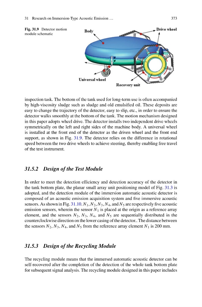
Fig. 31.9 Detector motion
module schematic
inspection task. The bottom of the tank used for long-term use is often accompanied
by high-viscosity sludge such as sludge and old emulsified oil. These deposits are
easy to change the trajectory of the detector, easy to slip, etc., in order to ensure the
detector walks smoothly at the bottom of the tank. The motion mechanism designed
in this paper adopts wheel drive. The detector installs two independent drive wheels
symmetrically on the left and right sides of the machine body. A universal wheel
is installed at the front end of the detector as the driven wheel and the front end
support, as shown in Fig. 31.9. The detector relies on the difference in rotational
speed between the two drive wheels to achieve steering, thereby enabling free travel
of the test instrument.
31.5.2 Design of the Test Module
In order to meet the detection efficiency and detection accuracy of the detector in
the tank bottom plate, the planar small array unit positioning model of Fig. 31.3 is
adopted, and the detection module of the immersion automatic acoustic detector is
composed of an acoustic emission acquisition system and five immersive acoustic
sensors. As shown in Fig. 31.10. N 1 , N 2 , N 3 , N 4 , and N 5 are respectively five acoustic
emission sensors, wherein the sensor N 1 is placed at the origin as a reference array
element, and the sensors N 2 , N 3 , N 4 , and N 5 are sequentially distributed in the
counterclockwise direction on the lower casing of the detector.. The distance between
the sensors N 2 , N 3 , N 4 , and N 5 from the reference array element N 1 is 200 mm.
31.5.3 Design of the Recycling Module
The recycling module means that the immersed automatic acoustic detector can be
self-recovered after the completion of the detection of the whole tank bottom plate
for subsequent signal analysis. The recycling module designed in this paper includes
373
Fig. 31.9 Detector motion
module schematic
inspection task. The bottom of the tank used for long-term use is often accompanied
by high-viscosity sludge such as sludge and old emulsified oil. These deposits are
easy to change the trajectory of the detector, easy to slip, etc., in order to ensure the
detector walks smoothly at the bottom of the tank. The motion mechanism designed
in this paper adopts wheel drive. The detector installs two independent drive wheels
symmetrically on the left and right sides of the machine body. A universal wheel
is installed at the front end of the detector as the driven wheel and the front end
support, as shown in Fig. 31.9. The detector relies on the difference in rotational
speed between the two drive wheels to achieve steering, thereby enabling free travel
of the test instrument.
31.5.2 Design of the Test Module
In order to meet the detection efficiency and detection accuracy of the detector in
the tank bottom plate, the planar small array unit positioning model of Fig. 31.3 is
adopted, and the detection module of the immersion automatic acoustic detector is
composed of an acoustic emission acquisition system and five immersive acoustic
sensors. As shown in Fig. 31.10. N 1 , N 2 , N 3 , N 4 , and N 5 are respectively five acoustic
emission sensors, wherein the sensor N 1 is placed at the origin as a reference array
element, and the sensors N 2 , N 3 , N 4 , and N 5 are sequentially distributed in the
counterclockwise direction on the lower casing of the detector.. The distance between
the sensors N 2 , N 3 , N 4 , and N 5 from the reference array element N 1 is 200 mm.
31.5.3 Design of the Recycling Module
The recycling module means that the immersed automatic acoustic detector can be
self-recovered after the completion of the detection of the whole tank bottom plate
for subsequent signal analysis. The recycling module designed in this paper includes