

368
J. Gao et al.
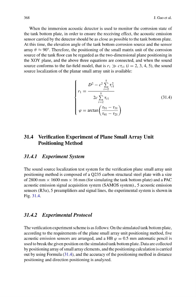
When the immersion acoustic detector is used to monitor the corrosion state of
the tank bottom plate, in order to ensure the receiving effect, the acoustic emission
sensor carried by the detector should be as close as possible to the tank bottom plate.
At this time, the elevation angle of the tank bottom corrosion source and the sensor
array θ ≈ 90°. Therefore, the positioning of the small matrix unit of the corrosion
source of the tank floor can be regarded as the two-dimensional plane positioning in
the XOY plane, and the above three equations are connected, and when the sound
source conforms to the far-field model, that is r 1 cτ i1 (i = 2, 3, 4, 5), the sound
source localization of the planar small array unit is available:
⎧
⎪ ⎪ ⎪ ⎪ ⎪ ⎪ ⎪ ⎨
⎪ ⎪ ⎪ ⎪ ⎪ ⎪ ⎪ ⎩
r 1 =
D
2
− c
2
5
i=2
τ
2
i1
2c
5
i=2
τ i1
ϕ = arctan
τ 51 − τ 31
τ 41 − τ 21
(31.4)
31.4 Verification Experiment of Plane Small Array Unit
Positioning Method
31.4.1 Experiment System
The sound source localization test system for the verification plane small array unit
positioning method is composed of a Q235 carbon structural steel plate with a size
of 2800 mm × 1600 mm × 16 mm (for simulating the tank bottom plate) and a PAC
acoustic emission signal acquisition system (SAMOS system)., 5 acoustic emission
sensors (R3α), 5 preamplifiers and signal lines, the experimental system is shown in
Fig. 31.4.
31.4.2 Experimental Protocol
The verification experiment scheme is as follows: On the simulated tank bottom plate,
according to the requirements of the plane small array unit positioning method, five
acoustic emission sensors are arranged, and a HB ϕ = 0.5 mm automatic pencil is
used to break the given position on the simulated tank bottom plate. Data are collected
by positioning array of small array elements, and the positioning calculation is carried
out by using Formula (31.4), and the accuracy of the positioning method in distance
positioning and direction positioning is analyzed.
J. Gao et al.
When the immersion acoustic detector is used to monitor the corrosion state of
the tank bottom plate, in order to ensure the receiving effect, the acoustic emission
sensor carried by the detector should be as close as possible to the tank bottom plate.
At this time, the elevation angle of the tank bottom corrosion source and the sensor
array θ ≈ 90°. Therefore, the positioning of the small matrix unit of the corrosion
source of the tank floor can be regarded as the two-dimensional plane positioning in
the XOY plane, and the above three equations are connected, and when the sound
source conforms to the far-field model, that is r 1 cτ i1 (i = 2, 3, 4, 5), the sound
source localization of the planar small array unit is available:
⎧
⎪ ⎪ ⎪ ⎪ ⎪ ⎪ ⎪ ⎨
⎪ ⎪ ⎪ ⎪ ⎪ ⎪ ⎪ ⎩
r 1 =
D
2
− c
2
5
i=2
τ
2
i1
2c
5
i=2
τ i1
ϕ = arctan
τ 51 − τ 31
τ 41 − τ 21
(31.4)
31.4 Verification Experiment of Plane Small Array Unit
Positioning Method
31.4.1 Experiment System
The sound source localization test system for the verification plane small array unit
positioning method is composed of a Q235 carbon structural steel plate with a size
of 2800 mm × 1600 mm × 16 mm (for simulating the tank bottom plate) and a PAC
acoustic emission signal acquisition system (SAMOS system)., 5 acoustic emission
sensors (R3α), 5 preamplifiers and signal lines, the experimental system is shown in
Fig. 31.4.
31.4.2 Experimental Protocol
The verification experiment scheme is as follows: On the simulated tank bottom plate,
according to the requirements of the plane small array unit positioning method, five
acoustic emission sensors are arranged, and a HB ϕ = 0.5 mm automatic pencil is
used to break the given position on the simulated tank bottom plate. Data are collected
by positioning array of small array elements, and the positioning calculation is carried
out by using Formula (31.4), and the accuracy of the positioning method in distance
positioning and direction positioning is analyzed.