

18 Investigation of Flexural Progressive …
207
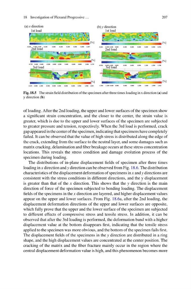
Fig. 18.5 The strain field distribution of the specimen after three times loading in x direction (a) and
y direction (b)
of loading. After the 2nd loading, the upper and lower surfaces of the specimen show
a significant strain concentration, and the closer to the center, the strain value is
greater, which is due to the upper and lower surfaces of the specimen are subjected
to greater pressure and tension, respectively. When the 3rd load is performed, crack
gap appeared in the center of the specimen, indicating that specimens have completely
failed. It can be observed that the value of high stress is distributed along the edge of
the crack, extending from the surface to the neutral layer, and some damages such as
matrix cracking, delamination and fiber breakage occurs at these stress concentration
locations. This reveals the stress condition and damage evolution process of the
specimen during loading.
The distributions of in-plane displacement fields of specimen after three times
loading in x direction and y direction can be observed from Fig. 18.6. The distribution
characteristics of the displacement deformation of specimens in x and y directions are
consistent with the stress conditions in different directions, and the y displacement
is greater than that of the x direction. This shows that the y direction is the main
direction of force of the specimen subjected to bending loading. The displacement
fields of the specimens in the x direction are layered, and higher displacement values
appear on the upper and lower surfaces. From Fig. 18.6a, after the 2nd loading, the
displacement deformation directions of the upper and lower surfaces are opposite,
which fully prove that the upper and the lower surface of the specimen are subjected
to different effects of compressive stress and tensile stress. In addition, it can be
observed that after the 3rd loading is performed, the deformation band with a higher
displacement value at the bottom disappears first, indicating that the tensile stress
applied to the specimen was more obvious, and the bottom of the specimen fails first.
The displacement fields of the specimens in the y direction are distributed in a ring
shape, and the high displacement values are concentrated at the center position. The
cracking of the matrix and the fiber fracture mainly occur in the region where the
central displacement deformation value is high, and this phenomenon becomes more
207
Fig. 18.5 The strain field distribution of the specimen after three times loading in x direction (a) and
y direction (b)
of loading. After the 2nd loading, the upper and lower surfaces of the specimen show
a significant strain concentration, and the closer to the center, the strain value is
greater, which is due to the upper and lower surfaces of the specimen are subjected
to greater pressure and tension, respectively. When the 3rd load is performed, crack
gap appeared in the center of the specimen, indicating that specimens have completely
failed. It can be observed that the value of high stress is distributed along the edge of
the crack, extending from the surface to the neutral layer, and some damages such as
matrix cracking, delamination and fiber breakage occurs at these stress concentration
locations. This reveals the stress condition and damage evolution process of the
specimen during loading.
The distributions of in-plane displacement fields of specimen after three times
loading in x direction and y direction can be observed from Fig. 18.6. The distribution
characteristics of the displacement deformation of specimens in x and y directions are
consistent with the stress conditions in different directions, and the y displacement
is greater than that of the x direction. This shows that the y direction is the main
direction of force of the specimen subjected to bending loading. The displacement
fields of the specimens in the x direction are layered, and higher displacement values
appear on the upper and lower surfaces. From Fig. 18.6a, after the 2nd loading, the
displacement deformation directions of the upper and lower surfaces are opposite,
which fully prove that the upper and the lower surface of the specimen are subjected
to different effects of compressive stress and tensile stress. In addition, it can be
observed that after the 3rd loading is performed, the deformation band with a higher
displacement value at the bottom disappears first, indicating that the tensile stress
applied to the specimen was more obvious, and the bottom of the specimen fails first.
The displacement fields of the specimens in the y direction are distributed in a ring
shape, and the high displacement values are concentrated at the center position. The
cracking of the matrix and the fiber fracture mainly occur in the region where the
central displacement deformation value is high, and this phenomenon becomes more