

Ellipsometry Techniques and Its Advanced Applications …
553
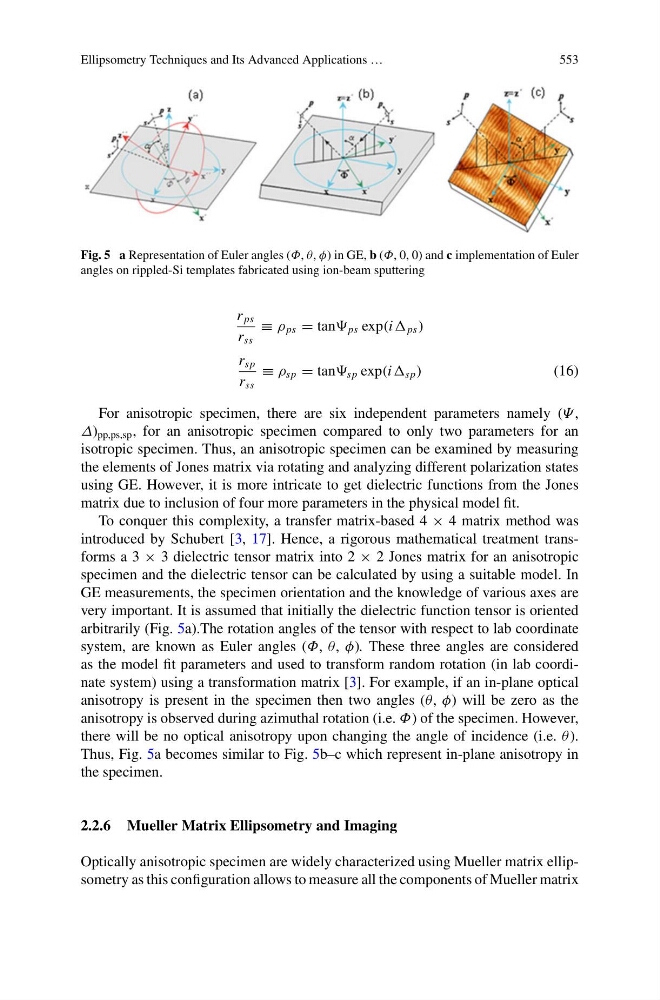
Fig. 5 a Representation of Euler angles (Φ, θ, φ) in GE, b (Φ, 0, 0) and c implementation of Euler
angles on rippled-Si templates fabricated using ion-beam sputtering
r ps
r ss
≡ ρ ps = tan ps exp(i ps )
r sp
r ss
≡ ρ sp = tan sp exp(i sp )
(16)
For anisotropic specimen, there are six independent parameters namely (Ψ ,
Δ) pp,ps,sp , for an anisotropic specimen compared to only two parameters for an
isotropic specimen. Thus, an anisotropic specimen can be examined by measuring
the elements of Jones matrix via rotating and analyzing different polarization states
using GE. However, it is more intricate to get dielectric functions from the Jones
matrix due to inclusion of four more parameters in the physical model fit.
To conquer this complexity, a transfer matrix-based 4 × 4 matrix method was
introduced by Schubert [3, 17]. Hence, a rigorous mathematical treatment transforms a 3 × 3 dielectric tensor matrix into 2 × 2 Jones matrix for an anisotropic
specimen and the dielectric tensor can be calculated by using a suitable model. In
GE measurements, the specimen orientation and the knowledge of various axes are
very important. It is assumed that initially the dielectric function tensor is oriented
arbitrarily (Fig. 5a).The rotation angles of the tensor with respect to lab coordinate
system, are known as Euler angles (Φ, θ, φ). These three angles are considered
as the model fit parameters and used to transform random rotation (in lab coordinate system) using a transformation matrix [3]. For example, if an in-plane optical
anisotropy is present in the specimen then two angles (θ, φ) will be zero as the
anisotropy is observed during azimuthal rotation (i.e. Φ) of the specimen. However,
there will be no optical anisotropy upon changing the angle of incidence (i.e. θ ).
Thus, Fig. 5a becomes similar to Fig. 5b–c which represent in-plane anisotropy in
the specimen.
2.2.6 Mueller Matrix Ellipsometry and Imaging
Optically anisotropic specimen are widely characterized using Mueller matrix ellipsometry as this configuration allows to measure all the components of Mueller matrix
553
Fig. 5 a Representation of Euler angles (Φ, θ, φ) in GE, b (Φ, 0, 0) and c implementation of Euler
angles on rippled-Si templates fabricated using ion-beam sputtering
r ps
r ss
≡ ρ ps = tan ps exp(i ps )
r sp
r ss
≡ ρ sp = tan sp exp(i sp )
(16)
For anisotropic specimen, there are six independent parameters namely (Ψ ,
Δ) pp,ps,sp , for an anisotropic specimen compared to only two parameters for an
isotropic specimen. Thus, an anisotropic specimen can be examined by measuring
the elements of Jones matrix via rotating and analyzing different polarization states
using GE. However, it is more intricate to get dielectric functions from the Jones
matrix due to inclusion of four more parameters in the physical model fit.
To conquer this complexity, a transfer matrix-based 4 × 4 matrix method was
introduced by Schubert [3, 17]. Hence, a rigorous mathematical treatment transforms a 3 × 3 dielectric tensor matrix into 2 × 2 Jones matrix for an anisotropic
specimen and the dielectric tensor can be calculated by using a suitable model. In
GE measurements, the specimen orientation and the knowledge of various axes are
very important. It is assumed that initially the dielectric function tensor is oriented
arbitrarily (Fig. 5a).The rotation angles of the tensor with respect to lab coordinate
system, are known as Euler angles (Φ, θ, φ). These three angles are considered
as the model fit parameters and used to transform random rotation (in lab coordinate system) using a transformation matrix [3]. For example, if an in-plane optical
anisotropy is present in the specimen then two angles (θ, φ) will be zero as the
anisotropy is observed during azimuthal rotation (i.e. Φ) of the specimen. However,
there will be no optical anisotropy upon changing the angle of incidence (i.e. θ ).
Thus, Fig. 5a becomes similar to Fig. 5b–c which represent in-plane anisotropy in
the specimen.
2.2.6 Mueller Matrix Ellipsometry and Imaging
Optically anisotropic specimen are widely characterized using Mueller matrix ellipsometry as this configuration allows to measure all the components of Mueller matrix