

552
M. Saini et al.
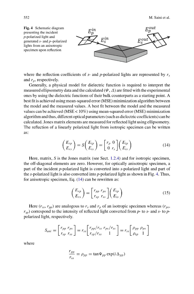
Fig. 4 Schematic diagram
presenting the incident
p-polarized light and
generated s- and p–polarized
lights from an anisotropic
specimen upon reflection
where the reflection coefficients of s- and p-polarized lights are represented by r s
and r p , respectively.
Generally, a physical model for dielectric function is required to interpret the
measured ellipsometry data and the calculated (Ψ , Δ) are fitted with the experimental
ones by using the dielectric functions of their bulk counterparts as a starting point. A
best fit is achieved using mean-squared error (MSE) minimization algorithm between
the model and the measured values. A best fit between the model and the measured
values can be achieved (MSE < 10%) using mean-squared error (MSE) minimization
algorithm and thus, different optical parameters (such as dielectric coefficients) can be
calculated. Jones matrix elements are measured for reflected light using ellipsometry.
The reflection of a linearly polarized light from isotropic specimen can be written
as:
E r p
E rs
= S
E i p
E is
=
r p 0
0 r s
E i p
E is
(14)
Here, matrix, S is the Jones matrix (see Sect. 1.2.4) and for isotropic specimen,
the off-diagonal elements are zero. However, for optically anisotropic specimen, a
part of the incident p-polarized light is converted into s-polarized light and part of
the s-polarized light is also converted into p-polarized light as shown in Fig. 4. Thus,
for anisotropic specimen, Eq. (14) can be rewritten as:
E r p
E rs
=
r pp r ps
r sp r ss
E i p
E is
(15)
Here (r ss , r pp ) are analogous to r s and r p of an isotropic specimen whereas (r ps ,
r sp ) correspond to the intensity of reflected light converted from p- to s- and s- to ppolarized light, respectively.
S ani =
r pp r ps
r sp r ss
= r ss
r pp /r ss r ps /r ss
r sp /r ss
1
= r ss
ρ pp ρ ps
ρ sp 1
where
r pp
r ss
≡ ρ pp = tan pp exp(i pp )
M. Saini et al.
Fig. 4 Schematic diagram
presenting the incident
p-polarized light and
generated s- and p–polarized
lights from an anisotropic
specimen upon reflection
where the reflection coefficients of s- and p-polarized lights are represented by r s
and r p , respectively.
Generally, a physical model for dielectric function is required to interpret the
measured ellipsometry data and the calculated (Ψ , Δ) are fitted with the experimental
ones by using the dielectric functions of their bulk counterparts as a starting point. A
best fit is achieved using mean-squared error (MSE) minimization algorithm between
the model and the measured values. A best fit between the model and the measured
values can be achieved (MSE < 10%) using mean-squared error (MSE) minimization
algorithm and thus, different optical parameters (such as dielectric coefficients) can be
calculated. Jones matrix elements are measured for reflected light using ellipsometry.
The reflection of a linearly polarized light from isotropic specimen can be written
as:
E r p
E rs
= S
E i p
E is
=
r p 0
0 r s
E i p
E is
(14)
Here, matrix, S is the Jones matrix (see Sect. 1.2.4) and for isotropic specimen,
the off-diagonal elements are zero. However, for optically anisotropic specimen, a
part of the incident p-polarized light is converted into s-polarized light and part of
the s-polarized light is also converted into p-polarized light as shown in Fig. 4. Thus,
for anisotropic specimen, Eq. (14) can be rewritten as:
E r p
E rs
=
r pp r ps
r sp r ss
E i p
E is
(15)
Here (r ss , r pp ) are analogous to r s and r p of an isotropic specimen whereas (r ps ,
r sp ) correspond to the intensity of reflected light converted from p- to s- and s- to ppolarized light, respectively.
S ani =
r pp r ps
r sp r ss
= r ss
r pp /r ss r ps /r ss
r sp /r ss
1
= r ss
ρ pp ρ ps
ρ sp 1
where
r pp
r ss
≡ ρ pp = tan pp exp(i pp )