

520
N. Yadav and R. Dhar
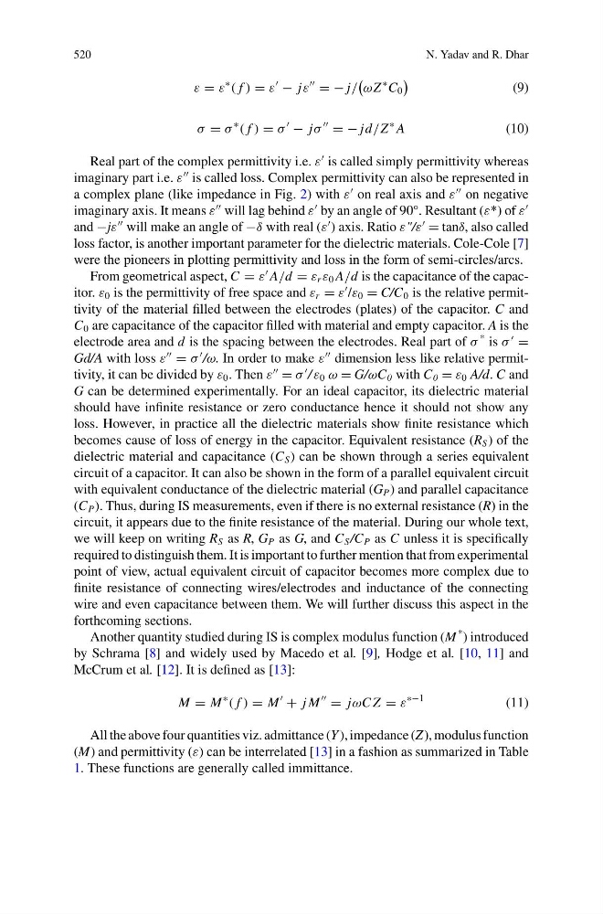
ε = ε
∗
( f ) = ε
− jε
= − j/
ωZ
∗ C 0
(9)
σ = σ
∗
( f ) = σ
− jσ
= − jd/Z
∗ A
(10)
Real part of the complex permittivity i.e. ε
is called simply permittivity whereas
imaginary part i.e. ε
is called loss. Complex permittivity can also be represented in
a complex plane (like impedance in Fig. 2) with ε
on real axis and ε
on negative
imaginary axis. It means ε
will lag behind ε
by an angle of 90°. Resultant (ε*) of ε
and −jε
will make an angle of −δ with real (ε
) axis. Ratio ε"/ε
= tanδ, also called
loss factor, is another important parameter for the dielectric materials. Cole-Cole [7]
were the pioneers in plotting permittivity and loss in the form of semi-circles/arcs.
From geometrical aspect, C = ε
A/d = ε r ε 0 A/d is the capacitance of the capacitor. ε 0 is the permittivity of free space and ε r = ε
/ε 0 = C/C 0 is the relative permittivity of the material filled between the electrodes (plates) of the capacitor. C and
C 0 are capacitance of the capacitor filled with material and empty capacitor. A is the
electrode area and d is the spacing between the electrodes. Real part of σ
* is σ
=
Gd/A with loss ε
= σ
/ω. In order to make ε
dimension less like relative permittivity, it can be divided by ε 0 . Then ε
= σ
/ ε 0 ω = G/ωC 0 with C 0 = ε 0 A/d. C and
G can be determined experimentally. For an ideal capacitor, its dielectric material
should have infinite resistance or zero conductance hence it should not show any
loss. However, in practice all the dielectric materials show finite resistance which
becomes cause of loss of energy in the capacitor. Equivalent resistance (R S ) of the
dielectric material and capacitance (C S ) can be shown through a series equivalent
circuit of a capacitor. It can also be shown in the form of a parallel equivalent circuit
with equivalent conductance of the dielectric material (G P ) and parallel capacitance
(C P ). Thus, during IS measurements, even if there is no external resistance (R) in the
circuit, it appears due to the finite resistance of the material. During our whole text,
we will keep on writing R S as R, G P as G, and C S /C P as C unless it is specifically
required to distinguish them. It is important to further mention that from experimental
point of view, actual equivalent circuit of capacitor becomes more complex due to
finite resistance of connecting wires/electrodes and inductance of the connecting
wire and even capacitance between them. We will further discuss this aspect in the
forthcoming sections.
Another quantity studied during IS is complex modulus function (M
* ) introduced
by Schrama [8] and widely used by Macedo et al. [9], Hodge et al. [10, 11] and
McCrum et al. [12]. It is defined as [13]:
M = M
∗
( f ) = M
+ j M
= jωC Z = ε
∗−1
(11)
All the above four quantities viz. admittance (Y ), impedance (Z), modulus function
(M) and permittivity (ε) can be interrelated [13] in a fashion as summarized in Table
1. These functions are generally called immittance.
N. Yadav and R. Dhar
ε = ε
∗
( f ) = ε
− jε
= − j/
ωZ
∗ C 0
(9)
σ = σ
∗
( f ) = σ
− jσ
= − jd/Z
∗ A
(10)
Real part of the complex permittivity i.e. ε
is called simply permittivity whereas
imaginary part i.e. ε
is called loss. Complex permittivity can also be represented in
a complex plane (like impedance in Fig. 2) with ε
on real axis and ε
on negative
imaginary axis. It means ε
will lag behind ε
by an angle of 90°. Resultant (ε*) of ε
and −jε
will make an angle of −δ with real (ε
) axis. Ratio ε"/ε
= tanδ, also called
loss factor, is another important parameter for the dielectric materials. Cole-Cole [7]
were the pioneers in plotting permittivity and loss in the form of semi-circles/arcs.
From geometrical aspect, C = ε
A/d = ε r ε 0 A/d is the capacitance of the capacitor. ε 0 is the permittivity of free space and ε r = ε
/ε 0 = C/C 0 is the relative permittivity of the material filled between the electrodes (plates) of the capacitor. C and
C 0 are capacitance of the capacitor filled with material and empty capacitor. A is the
electrode area and d is the spacing between the electrodes. Real part of σ
* is σ
=
Gd/A with loss ε
= σ
/ω. In order to make ε
dimension less like relative permittivity, it can be divided by ε 0 . Then ε
= σ
/ ε 0 ω = G/ωC 0 with C 0 = ε 0 A/d. C and
G can be determined experimentally. For an ideal capacitor, its dielectric material
should have infinite resistance or zero conductance hence it should not show any
loss. However, in practice all the dielectric materials show finite resistance which
becomes cause of loss of energy in the capacitor. Equivalent resistance (R S ) of the
dielectric material and capacitance (C S ) can be shown through a series equivalent
circuit of a capacitor. It can also be shown in the form of a parallel equivalent circuit
with equivalent conductance of the dielectric material (G P ) and parallel capacitance
(C P ). Thus, during IS measurements, even if there is no external resistance (R) in the
circuit, it appears due to the finite resistance of the material. During our whole text,
we will keep on writing R S as R, G P as G, and C S /C P as C unless it is specifically
required to distinguish them. It is important to further mention that from experimental
point of view, actual equivalent circuit of capacitor becomes more complex due to
finite resistance of connecting wires/electrodes and inductance of the connecting
wire and even capacitance between them. We will further discuss this aspect in the
forthcoming sections.
Another quantity studied during IS is complex modulus function (M
* ) introduced
by Schrama [8] and widely used by Macedo et al. [9], Hodge et al. [10, 11] and
McCrum et al. [12]. It is defined as [13]:
M = M
∗
( f ) = M
+ j M
= jωC Z = ε
∗−1
(11)
All the above four quantities viz. admittance (Y ), impedance (Z), modulus function
(M) and permittivity (ε) can be interrelated [13] in a fashion as summarized in Table
1. These functions are generally called immittance.