

Impedance Spectroscopy
519
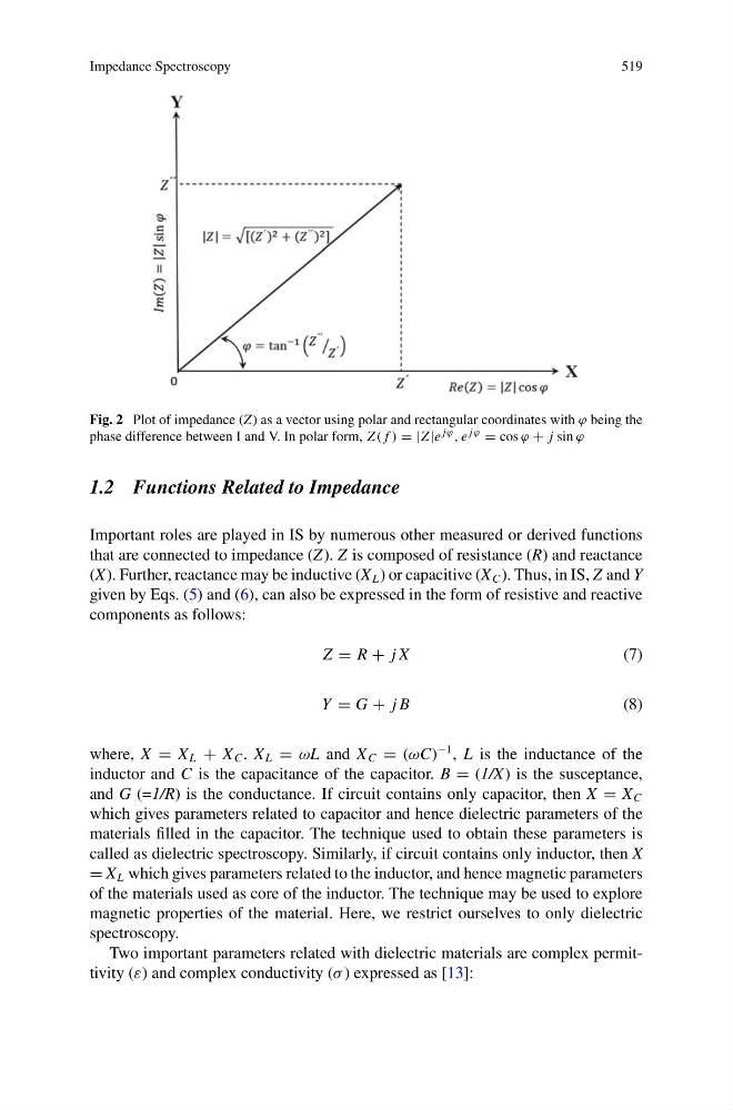
Fig. 2 Plot of impedance (Z) as a vector using polar and rectangular coordinates with ϕ being the
phase difference between I and V. In polar form, Z ( f ) = |Z |e jϕ , e jϕ = cos ϕ + j sin ϕ
1.2 Functions Related to Impedance
Important roles are played in IS by numerous other measured or derived functions
that are connected to impedance (Z). Z is composed of resistance (R) and reactance
(X). Further, reactance may be inductive (X L ) or capacitive (X C ). Thus, in IS, Z and Y
given by Eqs. (5) and (6), can also be expressed in the form of resistive and reactive
components as follows:
Z = R + j X
(7)
Y = G + j B
(8)
where, X = X L + X C . X L = ωL and X C = (ωC)
−1 , L is the inductance of the
inductor and C is the capacitance of the capacitor. B = (1/X) is the susceptance,
and G (=1/R) is the conductance. If circuit contains only capacitor, then X = X C
which gives parameters related to capacitor and hence dielectric parameters of the
materials filled in the capacitor. The technique used to obtain these parameters is
called as dielectric spectroscopy. Similarly, if circuit contains only inductor, then X
= X L which gives parameters related to the inductor, and hence magnetic parameters
of the materials used as core of the inductor. The technique may be used to explore
magnetic properties of the material. Here, we restrict ourselves to only dielectric
spectroscopy.
Two important parameters related with dielectric materials are complex permittivity (ε) and complex conductivity (σ ) expressed as [13]:
519
Fig. 2 Plot of impedance (Z) as a vector using polar and rectangular coordinates with ϕ being the
phase difference between I and V. In polar form, Z ( f ) = |Z |e jϕ , e jϕ = cos ϕ + j sin ϕ
1.2 Functions Related to Impedance
Important roles are played in IS by numerous other measured or derived functions
that are connected to impedance (Z). Z is composed of resistance (R) and reactance
(X). Further, reactance may be inductive (X L ) or capacitive (X C ). Thus, in IS, Z and Y
given by Eqs. (5) and (6), can also be expressed in the form of resistive and reactive
components as follows:
Z = R + j X
(7)
Y = G + j B
(8)
where, X = X L + X C . X L = ωL and X C = (ωC)
−1 , L is the inductance of the
inductor and C is the capacitance of the capacitor. B = (1/X) is the susceptance,
and G (=1/R) is the conductance. If circuit contains only capacitor, then X = X C
which gives parameters related to capacitor and hence dielectric parameters of the
materials filled in the capacitor. The technique used to obtain these parameters is
called as dielectric spectroscopy. Similarly, if circuit contains only inductor, then X
= X L which gives parameters related to the inductor, and hence magnetic parameters
of the materials used as core of the inductor. The technique may be used to explore
magnetic properties of the material. Here, we restrict ourselves to only dielectric
spectroscopy.
Two important parameters related with dielectric materials are complex permittivity (ε) and complex conductivity (σ ) expressed as [13]: