

Modern Experimental Techniques in Ultrafast Atomic …
281
Fig. 21 Schematic diagram of Eppink and Parker’s three plates VMI spectrometer
The ions formed in the ionization region are repelled by the repeller plate directed
along the VMI axis, towards the extractor plate. The extractor plate(s) pulls the ions
or electrons towards the ground plate. The charged particles drift in the field-free
region (ground) according to their energies and finally hit the 2D MCP-phosphor
detector.
The photoelectrons produced during the ionization are mapped on to the position
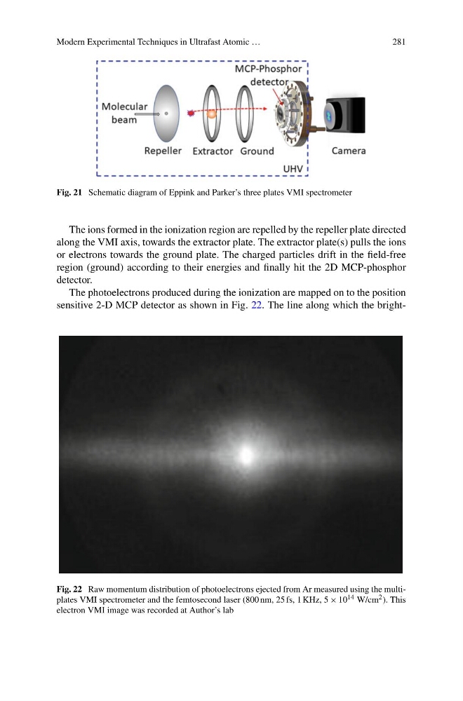
sensitive 2-D MCP detector as shown in Fig. 22. The line along which the brightFig. 22 Raw momentum distribution of photoelectrons ejected from Ar measured using the multiplates VMI spectrometer and the femtosecond laser (800 nm, 25 fs, 1 KHz, 5 × 10 14 W/cm 2 ). This
electron VMI image was recorded at Author’s lab
281
Fig. 21 Schematic diagram of Eppink and Parker’s three plates VMI spectrometer
The ions formed in the ionization region are repelled by the repeller plate directed
along the VMI axis, towards the extractor plate. The extractor plate(s) pulls the ions
or electrons towards the ground plate. The charged particles drift in the field-free
region (ground) according to their energies and finally hit the 2D MCP-phosphor
detector.
The photoelectrons produced during the ionization are mapped on to the position
sensitive 2-D MCP detector as shown in Fig. 22. The line along which the brightFig. 22 Raw momentum distribution of photoelectrons ejected from Ar measured using the multiplates VMI spectrometer and the femtosecond laser (800 nm, 25 fs, 1 KHz, 5 × 10 14 W/cm 2 ). This
electron VMI image was recorded at Author’s lab