

Modern Experimental Techniques in Ultrafast Atomic …
261
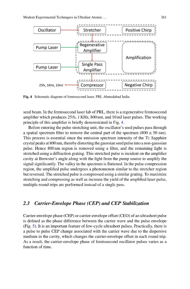
Fig. 4 Schematic diagram of femtosecond laser, PRL Ahmedabad India
seed beam. In the femtosecond laser lab of PRL, there is a regenerative femtosecond
amplifier which produces 25 fs, 1 KHz, 800 nm, and 10 mJ laser pulses. The working
principle of this amplifier is briefly demonstrated in Fig. 4.
Before entering the pulse stretching unit, the oscillator’s seed pulses pass through
a spatial spectrum filter to remove the central part of the spectrum (800 ± 50 nm).
This process is essential since the emission spectrum intensity of the Ti: Sapphire
crystal peaks at 800 nm, thereby distorting the gaussian seed pulse into a non-gaussian
pulse. Hence 800 nm region is removed using a filter, and the remaining light is
stretched using a diffraction grating. This stretched pulse is incident on the amplifier
cavity at Brewster’s angle along with the light from the pump source to amplify the
signal significantly. The valley in the spectrum is flattened. In the pulse compression
region, the amplified pulse undergoes a phenomenon similar to the stretcher region
but reversed. The stretched pulse is compressed using a similar grating. To maximize
stretching and compressing as well as increase the yield of the amplified laser pulse,
multiple round-trips are performed instead of a single pass.
2.3 Carrier-Envelope Phase (CEP) and CEP Stabilization
Carrier-envelope phase (CEP) or carrier-envelope offset (CEO) of an ultrashort pulse
is defined as the phase difference between the carrier wave and the pulse envelope
(Fig. 5). It is an important feature of few-cycle ultrashort pulses. Practically, there is
a pulse to pulse CEP change associated with the carrier wave due to the dispersive
medium in the cavity, which changes the carrier-envelope offset in each round trip.
As a result, the carrier-envelope phase of femtosecond oscillator pulses varies as a
function of time.
261
Fig. 4 Schematic diagram of femtosecond laser, PRL Ahmedabad India
seed beam. In the femtosecond laser lab of PRL, there is a regenerative femtosecond
amplifier which produces 25 fs, 1 KHz, 800 nm, and 10 mJ laser pulses. The working
principle of this amplifier is briefly demonstrated in Fig. 4.
Before entering the pulse stretching unit, the oscillator’s seed pulses pass through
a spatial spectrum filter to remove the central part of the spectrum (800 ± 50 nm).
This process is essential since the emission spectrum intensity of the Ti: Sapphire
crystal peaks at 800 nm, thereby distorting the gaussian seed pulse into a non-gaussian
pulse. Hence 800 nm region is removed using a filter, and the remaining light is
stretched using a diffraction grating. This stretched pulse is incident on the amplifier
cavity at Brewster’s angle along with the light from the pump source to amplify the
signal significantly. The valley in the spectrum is flattened. In the pulse compression
region, the amplified pulse undergoes a phenomenon similar to the stretcher region
but reversed. The stretched pulse is compressed using a similar grating. To maximize
stretching and compressing as well as increase the yield of the amplified laser pulse,
multiple round-trips are performed instead of a single pass.
2.3 Carrier-Envelope Phase (CEP) and CEP Stabilization
Carrier-envelope phase (CEP) or carrier-envelope offset (CEO) of an ultrashort pulse
is defined as the phase difference between the carrier wave and the pulse envelope
(Fig. 5). It is an important feature of few-cycle ultrashort pulses. Practically, there is
a pulse to pulse CEP change associated with the carrier wave due to the dispersive
medium in the cavity, which changes the carrier-envelope offset in each round trip.
As a result, the carrier-envelope phase of femtosecond oscillator pulses varies as a
function of time.