

36
4 Plasma of Magnetic Monopoles
thermal
energy
hole
electron
Valence band
Conduction band
Generation
Recombination
thermal
energy
Generation
hole
electron
Valence band
Conduction band
thermal
energy
Recombination
a
b
Electronic band structure
Spin Ice manifold
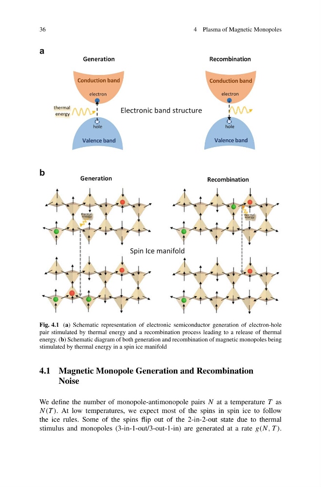
Fig. 4.1 (a) Schematic representation of electronic semiconductor generation of electron-hole
pair stimulated by thermal energy and a recombination process leading to a release of thermal
energy. (b) Schematic diagram of both generation and recombination of magnetic monopoles being
stimulated by thermal energy in a spin ice manifold
4.1 Magnetic Monopole Generation and Recombination
Noise
We define the number of monopole-antimonopole pairs N at a temperature T as
N(T ). At low temperatures, we expect most of the spins in spin ice to follow
the ice rules. Some of the spins flip out of the 2-in-2-out state due to thermal
stimulus and monopoles (3-in-1-out/3-out-1-in) are generated at a rate g(N, T ).
4 Plasma of Magnetic Monopoles
thermal
energy
hole
electron
Valence band
Conduction band
Generation
Recombination
thermal
energy
Generation
hole
electron
Valence band
Conduction band
thermal
energy
Recombination
a
b
Electronic band structure
Spin Ice manifold
Fig. 4.1 (a) Schematic representation of electronic semiconductor generation of electron-hole
pair stimulated by thermal energy and a recombination process leading to a release of thermal
energy. (b) Schematic diagram of both generation and recombination of magnetic monopoles being
stimulated by thermal energy in a spin ice manifold
4.1 Magnetic Monopole Generation and Recombination
Noise
We define the number of monopole-antimonopole pairs N at a temperature T as
N(T ). At low temperatures, we expect most of the spins in spin ice to follow
the ice rules. Some of the spins flip out of the 2-in-2-out state due to thermal
stimulus and monopoles (3-in-1-out/3-out-1-in) are generated at a rate g(N, T ).