

312
16 Hyperbolic Radio Navigation Systems
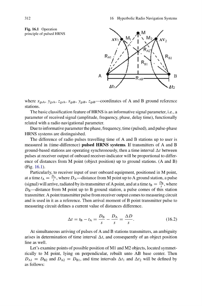
Fig. 16.1 Operation
principle of pulsed HRNS
where x gsA , y gsA , z gsA , x gsB , y gsB , z gsB —coordinates of A and B ground reference
stations.
The basic classification feature of HRNS is an informative signal parameter, i.e., a
parameter of received signal (amplitude, frequency, phase, delay time), functionally
related with a radio navigational parameter.
Due to informative parameter the phase, frequency, time (pulsed), and pulse-phase
HRNS systems are distinguished.
The difference of radio pulses travelling time of A and B stations up to user is
measured in (time-difference) pulsed HRNS systems. If transmitters of A and B
ground-based stations are operating synchronously, then a time interval t between
pulses at receiver output of onboard receiver-indicator will be proportional to difference of distances from M point (object position) up to ground stations. (A and B)
(Fig. 16.1).
Particularly, to receiver input of user onboard equipment, positioned in M point,
at a time t A =
D A
s
, where D A —distance from M point up to A ground station, a pulse
(signal) will arrive, radiated by its transmitter of A point, and at a time t B =
D B
s
, where
D B —distance from M point up to B ground station, a pulse comes of this station
transmitter. A point transmitter pulse from receiver output comes to measuring circuit
and is used in it as a reference. Then arrival moment of B point transmitter pulse to
measuring circuit defines a current value of distances difference.
t = t B − t A =
D B
s
−
D A
s
=
D
s
.
(16.2)
At simultaneous arriving of pulses of A and B stations transmitters, an ambiguity
arises in determination of time interval t, and consequently of an object position
line as well.
Let’s examine points of possible position of M1 and M2 objects, located symmetrically to M point, lying on perpendicular, rebuilt unto AB base center. Then
D A1 = D B2 and D A2 = D B1 , and time intervals t 1 and t 2 will be defined by
as follows:
16 Hyperbolic Radio Navigation Systems
Fig. 16.1 Operation
principle of pulsed HRNS
where x gsA , y gsA , z gsA , x gsB , y gsB , z gsB —coordinates of A and B ground reference
stations.
The basic classification feature of HRNS is an informative signal parameter, i.e., a
parameter of received signal (amplitude, frequency, phase, delay time), functionally
related with a radio navigational parameter.
Due to informative parameter the phase, frequency, time (pulsed), and pulse-phase
HRNS systems are distinguished.
The difference of radio pulses travelling time of A and B stations up to user is
measured in (time-difference) pulsed HRNS systems. If transmitters of A and B
ground-based stations are operating synchronously, then a time interval t between
pulses at receiver output of onboard receiver-indicator will be proportional to difference of distances from M point (object position) up to ground stations. (A and B)
(Fig. 16.1).
Particularly, to receiver input of user onboard equipment, positioned in M point,
at a time t A =
D A
s
, where D A —distance from M point up to A ground station, a pulse
(signal) will arrive, radiated by its transmitter of A point, and at a time t B =
D B
s
, where
D B —distance from M point up to B ground station, a pulse comes of this station
transmitter. A point transmitter pulse from receiver output comes to measuring circuit
and is used in it as a reference. Then arrival moment of B point transmitter pulse to
measuring circuit defines a current value of distances difference.
t = t B − t A =
D B
s
−
D A
s
=
D
s
.
(16.2)
At simultaneous arriving of pulses of A and B stations transmitters, an ambiguity
arises in determination of time interval t, and consequently of an object position
line as well.
Let’s examine points of possible position of M1 and M2 objects, located symmetrically to M point, lying on perpendicular, rebuilt unto AB base center. Then
D A1 = D B2 and D A2 = D B1 , and time intervals t 1 and t 2 will be defined by
as follows: