

15.1 Radio Beacon Goniometric Radio Navigation Systems
305
Table 15.2 ADF technical specifications
Parameter description
ADF-75
ADF-80
ADF-95
DF-2000
Bandwidth, MHz
118–136
118–136
118–136.975
118–137
Operational range, km
H = 1000 m
H = 3000 m
H = 10,000 m
–
–
100
120
–
–
180
200
300
200
300
360
Bearing error, deg.
1
1.5
1
1
Channels no
1–8
1–2
2–16
2–16
center that leads to, due to Doppler effect, frequency change of receiving signal. In
this case, pseudo-Doppler effect concludes in that at switching moment a phase of
receiving signal is jump-like changed, and joint curve of phase change, consisting
of discrete points, repeats a Doppler envelope. All modern airdrome radio directionfinders are constructed on the base of such quasi-Doppler principle and hence are
related to Doppler phase direction-finders.
Re-reflections from ground features effect in general on bearing accuracy of
Doppler automatic direction-finders (ADF), and including signals, which are close
in frequency to ADF operating frequency. Hence, direction-finders are installed in
airdrome area, on the terrain away from reradiators (power transmission lines, highrise structures, trees, etc.) with regard to requirements for ensuring of electromagnetic
compatibility.
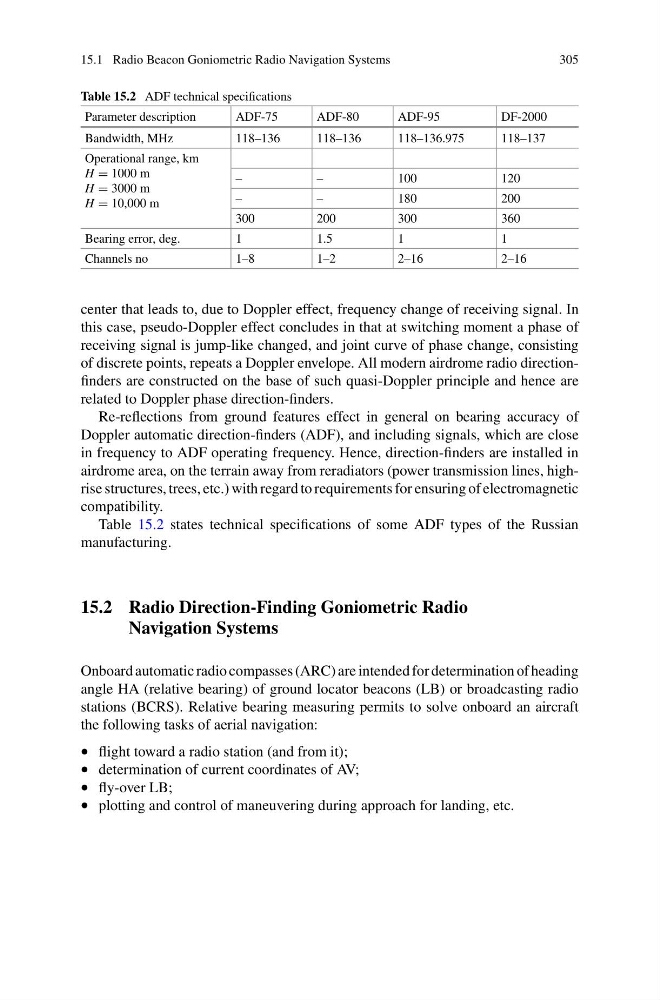
Table 15.2 states technical specifications of some ADF types of the Russian
manufacturing.
15.2 Radio Direction-Finding Goniometric Radio
Navigation Systems
Onboard automatic radio compasses (ARC) are intended for determination of heading
angle HA (relative bearing) of ground locator beacons (LB) or broadcasting radio
stations (BCRS). Relative bearing measuring permits to solve onboard an aircraft
the following tasks of aerial navigation:
• flight toward a radio station (and from it);
• determination of current coordinates of AV;
• fly-over LB;
• plotting and control of maneuvering during approach for landing, etc.
305
Table 15.2 ADF technical specifications
Parameter description
ADF-75
ADF-80
ADF-95
DF-2000
Bandwidth, MHz
118–136
118–136
118–136.975
118–137
Operational range, km
H = 1000 m
H = 3000 m
H = 10,000 m
–
–
100
120
–
–
180
200
300
200
300
360
Bearing error, deg.
1
1.5
1
1
Channels no
1–8
1–2
2–16
2–16
center that leads to, due to Doppler effect, frequency change of receiving signal. In
this case, pseudo-Doppler effect concludes in that at switching moment a phase of
receiving signal is jump-like changed, and joint curve of phase change, consisting
of discrete points, repeats a Doppler envelope. All modern airdrome radio directionfinders are constructed on the base of such quasi-Doppler principle and hence are
related to Doppler phase direction-finders.
Re-reflections from ground features effect in general on bearing accuracy of
Doppler automatic direction-finders (ADF), and including signals, which are close
in frequency to ADF operating frequency. Hence, direction-finders are installed in
airdrome area, on the terrain away from reradiators (power transmission lines, highrise structures, trees, etc.) with regard to requirements for ensuring of electromagnetic
compatibility.
Table 15.2 states technical specifications of some ADF types of the Russian
manufacturing.
15.2 Radio Direction-Finding Goniometric Radio
Navigation Systems
Onboard automatic radio compasses (ARC) are intended for determination of heading
angle HA (relative bearing) of ground locator beacons (LB) or broadcasting radio
stations (BCRS). Relative bearing measuring permits to solve onboard an aircraft
the following tasks of aerial navigation:
• flight toward a radio station (and from it);
• determination of current coordinates of AV;
• fly-over LB;
• plotting and control of maneuvering during approach for landing, etc.