

304
15 Goniometric Radio Navigation Systems
Thereby, the initial phase of Doppler frequency dependence from time (radiator
slewing angle) is defined by a bearing to an aircraft. In general, the Doppler frequency
value, due to antenna rotation in circular, comprises:
F D (t) =
2ππ r R sin(2ππ r t − α)
λ
,
(15.34)
where R—radiator rotation radius; r —antenna rotation velocity; α—aircraft
bearing; λ—wavelength of HF oscillations.
In receiver, it is possible to extract this frequency changing law in the form of
voltage or signal, changes with antenna rotation frequency. Extraction is carried out
by comparison in frequency of HF oscillations, picked out from rotating antenna
and oscillations from non-directional antenna. Phase of extracted signal depends on
direction to an aircraft, and hence, this signal is called a “variable phase” signal.
It is possible to measure a phase of this signal only by comparison with a phase
of another reference signal, the phase of which will not depend on aircraft bearing.
Consequently, a signal is called “uniform (constant) phase” signal. “Uniform phase”
signal in radio direction-finder is formed by reference oscillator.
Radio direction-finder is adjusted in that way that phases of signals will coincide
in direction to north. In any other direction, a phase of “variable phase” signal falls
back from a phase of “uniform phase” signal at an angle between this direction and
direction to north. Consequently, by measuring a value of such backward it is possible
to determine an object bearing.
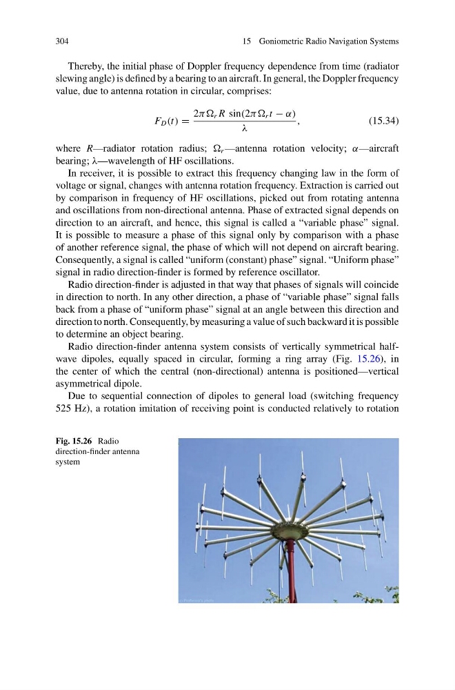
Radio direction-finder antenna system consists of vertically symmetrical halfwave dipoles, equally spaced in circular, forming a ring array (Fig. 15.26), in
the center of which the central (non-directional) antenna is positioned—vertical
asymmetrical dipole.
Due to sequential connection of dipoles to general load (switching frequency
525 Hz), a rotation imitation of receiving point is conducted relatively to rotation
Fig. 15.26 Radio
direction-finder antenna
system
15 Goniometric Radio Navigation Systems
Thereby, the initial phase of Doppler frequency dependence from time (radiator
slewing angle) is defined by a bearing to an aircraft. In general, the Doppler frequency
value, due to antenna rotation in circular, comprises:
F D (t) =
2ππ r R sin(2ππ r t − α)
λ
,
(15.34)
where R—radiator rotation radius; r —antenna rotation velocity; α—aircraft
bearing; λ—wavelength of HF oscillations.
In receiver, it is possible to extract this frequency changing law in the form of
voltage or signal, changes with antenna rotation frequency. Extraction is carried out
by comparison in frequency of HF oscillations, picked out from rotating antenna
and oscillations from non-directional antenna. Phase of extracted signal depends on
direction to an aircraft, and hence, this signal is called a “variable phase” signal.
It is possible to measure a phase of this signal only by comparison with a phase
of another reference signal, the phase of which will not depend on aircraft bearing.
Consequently, a signal is called “uniform (constant) phase” signal. “Uniform phase”
signal in radio direction-finder is formed by reference oscillator.
Radio direction-finder is adjusted in that way that phases of signals will coincide
in direction to north. In any other direction, a phase of “variable phase” signal falls
back from a phase of “uniform phase” signal at an angle between this direction and
direction to north. Consequently, by measuring a value of such backward it is possible
to determine an object bearing.
Radio direction-finder antenna system consists of vertically symmetrical halfwave dipoles, equally spaced in circular, forming a ring array (Fig. 15.26), in
the center of which the central (non-directional) antenna is positioned—vertical
asymmetrical dipole.
Due to sequential connection of dipoles to general load (switching frequency
525 Hz), a rotation imitation of receiving point is conducted relatively to rotation
Fig. 15.26 Radio
direction-finder antenna
system