

15.1 Radio Beacon Goniometric Radio Navigation Systems
303
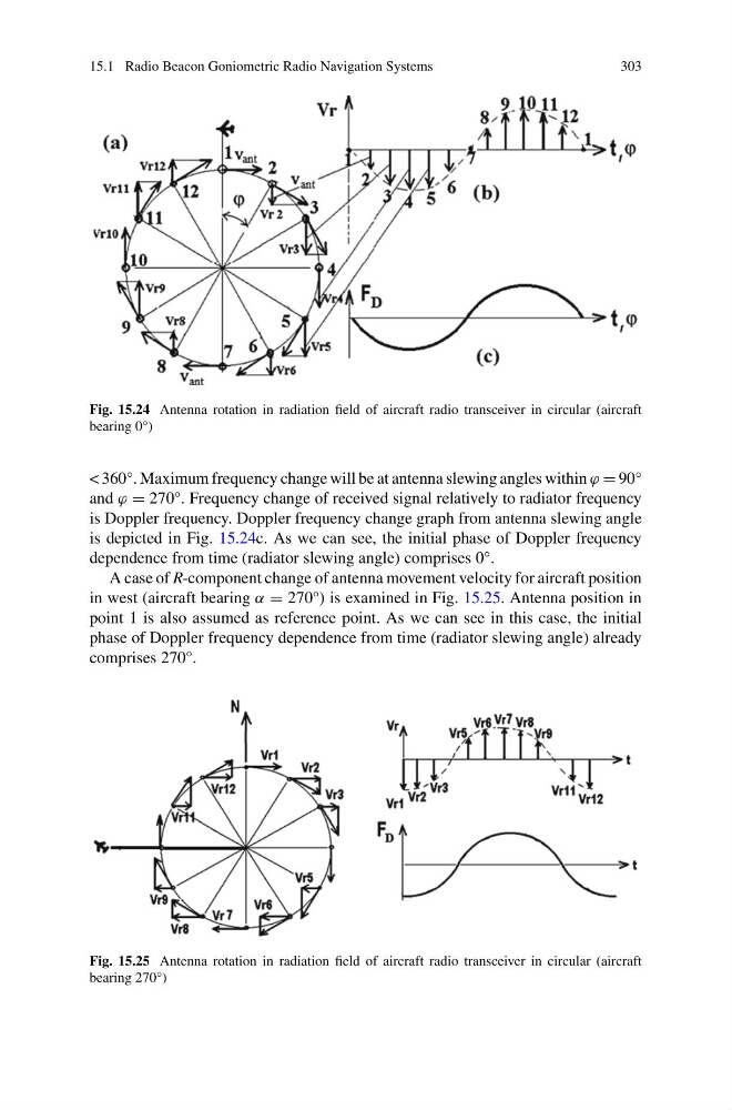
Fig. 15.24 Antenna rotation in radiation field of aircraft radio transceiver in circular (aircraft
bearing 0°)
< 360°. Maximum frequency change will be at antenna slewing angles within ϕ = 90°
and ϕ = 270°. Frequency change of received signal relatively to radiator frequency
is Doppler frequency. Doppler frequency change graph from antenna slewing angle
is depicted in Fig. 15.24c. As we can see, the initial phase of Doppler frequency
dependence from time (radiator slewing angle) comprises 0°.
A case of R-component change of antenna movement velocity for aircraft position
in west (aircraft bearing α = 270°) is examined in Fig. 15.25. Antenna position in
point 1 is also assumed as reference point. As we can see in this case, the initial
phase of Doppler frequency dependence from time (radiator slewing angle) already
comprises 270°.
Fig. 15.25 Antenna rotation in radiation field of aircraft radio transceiver in circular (aircraft
bearing 270°)
303
Fig. 15.24 Antenna rotation in radiation field of aircraft radio transceiver in circular (aircraft
bearing 0°)
< 360°. Maximum frequency change will be at antenna slewing angles within ϕ = 90°
and ϕ = 270°. Frequency change of received signal relatively to radiator frequency
is Doppler frequency. Doppler frequency change graph from antenna slewing angle
is depicted in Fig. 15.24c. As we can see, the initial phase of Doppler frequency
dependence from time (radiator slewing angle) comprises 0°.
A case of R-component change of antenna movement velocity for aircraft position
in west (aircraft bearing α = 270°) is examined in Fig. 15.25. Antenna position in
point 1 is also assumed as reference point. As we can see in this case, the initial
phase of Doppler frequency dependence from time (radiator slewing angle) already
comprises 270°.
Fig. 15.25 Antenna rotation in radiation field of aircraft radio transceiver in circular (aircraft
bearing 270°)