

302
15 Goniometric Radio Navigation Systems
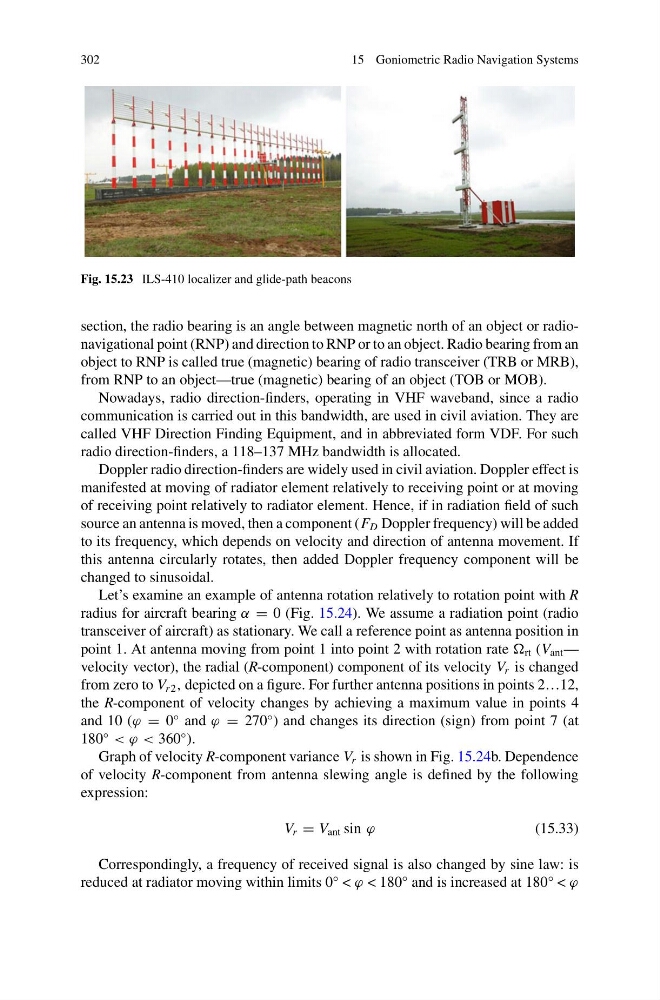
Fig. 15.23 ILS-410 localizer and glide-path beacons
section, the radio bearing is an angle between magnetic north of an object or radionavigational point (RNP) and direction to RNP or to an object. Radio bearing from an
object to RNP is called true (magnetic) bearing of radio transceiver (TRB or MRB),
from RNP to an object—true (magnetic) bearing of an object (TOB or MOB).
Nowadays, radio direction-finders, operating in VHF waveband, since a radio
communication is carried out in this bandwidth, are used in civil aviation. They are
called VHF Direction Finding Equipment, and in abbreviated form VDF. For such
radio direction-finders, a 118–137 MHz bandwidth is allocated.
Doppler radio direction-finders are widely used in civil aviation. Doppler effect is
manifested at moving of radiator element relatively to receiving point or at moving
of receiving point relatively to radiator element. Hence, if in radiation field of such
source an antenna is moved, then a component (F D Doppler frequency) will be added
to its frequency, which depends on velocity and direction of antenna movement. If
this antenna circularly rotates, then added Doppler frequency component will be
changed to sinusoidal.
Let’s examine an example of antenna rotation relatively to rotation point with R
radius for aircraft bearing α = 0 (Fig. 15.24). We assume a radiation point (radio
transceiver of aircraft) as stationary. We call a reference point as antenna position in
point 1. At antenna moving from point 1 into point 2 with rotation rate rt (V ant —
velocity vector), the radial (R-component) component of its velocity V r is changed
from zero to V r 2 , depicted on a figure. For further antenna positions in points 2…12,
the R-component of velocity changes by achieving a maximum value in points 4
and 10 (ϕ = 0
◦ and ϕ = 270
◦ ) and changes its direction (sign) from point 7 (at
180
◦
< ϕ < 360
◦ ).
Graph of velocity R-component variance V r is shown in Fig. 15.24b. Dependence
of velocity R-component from antenna slewing angle is defined by the following
expression:
V r = V ant sin ϕ
(15.33)
Correspondingly, a frequency of received signal is also changed by sine law: is
reduced at radiator moving within limits 0° < ϕ < 180° and is increased at 180° < ϕ
15 Goniometric Radio Navigation Systems
Fig. 15.23 ILS-410 localizer and glide-path beacons
section, the radio bearing is an angle between magnetic north of an object or radionavigational point (RNP) and direction to RNP or to an object. Radio bearing from an
object to RNP is called true (magnetic) bearing of radio transceiver (TRB or MRB),
from RNP to an object—true (magnetic) bearing of an object (TOB or MOB).
Nowadays, radio direction-finders, operating in VHF waveband, since a radio
communication is carried out in this bandwidth, are used in civil aviation. They are
called VHF Direction Finding Equipment, and in abbreviated form VDF. For such
radio direction-finders, a 118–137 MHz bandwidth is allocated.
Doppler radio direction-finders are widely used in civil aviation. Doppler effect is
manifested at moving of radiator element relatively to receiving point or at moving
of receiving point relatively to radiator element. Hence, if in radiation field of such
source an antenna is moved, then a component (F D Doppler frequency) will be added
to its frequency, which depends on velocity and direction of antenna movement. If
this antenna circularly rotates, then added Doppler frequency component will be
changed to sinusoidal.
Let’s examine an example of antenna rotation relatively to rotation point with R
radius for aircraft bearing α = 0 (Fig. 15.24). We assume a radiation point (radio
transceiver of aircraft) as stationary. We call a reference point as antenna position in
point 1. At antenna moving from point 1 into point 2 with rotation rate rt (V ant —
velocity vector), the radial (R-component) component of its velocity V r is changed
from zero to V r 2 , depicted on a figure. For further antenna positions in points 2…12,
the R-component of velocity changes by achieving a maximum value in points 4
and 10 (ϕ = 0
◦ and ϕ = 270
◦ ) and changes its direction (sign) from point 7 (at
180
◦
< ϕ < 360
◦ ).
Graph of velocity R-component variance V r is shown in Fig. 15.24b. Dependence
of velocity R-component from antenna slewing angle is defined by the following
expression:
V r = V ant sin ϕ
(15.33)
Correspondingly, a frequency of received signal is also changed by sine law: is
reduced at radiator moving within limits 0° < ϕ < 180° and is increased at 180° < ϕ