

15.1 Radio Beacon Goniometric Radio Navigation Systems
301
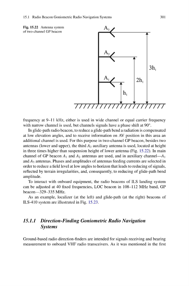
Fig. 15.22 Antenna system
of two-channel GP beacon
frequency at 9–11 kHz, either is used in wide channel or equal carrier frequency
with narrow channel is used, but channels signals have a phase shift at 90°.
In glide-path radio beacon, to reduce a glide-path bend a radiation is compensated
at low elevation angles, and to receive information on AV position in this area an
additional channel is used. For this purpose in two-channel GP beacon, besides two
antennas (lower and upper), the third A 3 auxiliary antenna is used, located at height
in three times higher than suspension height of lower antenna (Fig. 15.22). In main
channel of GP beacon A 1 and A 2 antennas are used, and in auxiliary channel—A 1
and A 3 antennas. Phases and amplitudes of antennas feeding currents are selected in
order to reduce a field level at low angles to horizon that leads to reducing of signals,
reflected by terrain irregularities, and, consequently, to reducing of glide-path bend
amplitude.
To interact with onboard equipment, the radio beacons of ILS landing system
can be adjusted at 40 fixed frequencies, LOC beacon in 108–112 MHz band, GP
beacon—329–335 MHz.
As an example, localizer (at the left) and glide-path (at the right) beacons of
ILS-410 system are illustrated in Fig. 15.23.
15.1.1 Direction-Finding Goniometric Radio Navigation
Systems
Ground-based radio direction-finders are intended for signals receiving and bearing
measurement to onboard VHF radio transceivers. As it was mentioned in the first
301
Fig. 15.22 Antenna system
of two-channel GP beacon
frequency at 9–11 kHz, either is used in wide channel or equal carrier frequency
with narrow channel is used, but channels signals have a phase shift at 90°.
In glide-path radio beacon, to reduce a glide-path bend a radiation is compensated
at low elevation angles, and to receive information on AV position in this area an
additional channel is used. For this purpose in two-channel GP beacon, besides two
antennas (lower and upper), the third A 3 auxiliary antenna is used, located at height
in three times higher than suspension height of lower antenna (Fig. 15.22). In main
channel of GP beacon A 1 and A 2 antennas are used, and in auxiliary channel—A 1
and A 3 antennas. Phases and amplitudes of antennas feeding currents are selected in
order to reduce a field level at low angles to horizon that leads to reducing of signals,
reflected by terrain irregularities, and, consequently, to reducing of glide-path bend
amplitude.
To interact with onboard equipment, the radio beacons of ILS landing system
can be adjusted at 40 fixed frequencies, LOC beacon in 108–112 MHz band, GP
beacon—329–335 MHz.
As an example, localizer (at the left) and glide-path (at the right) beacons of
ILS-410 system are illustrated in Fig. 15.23.
15.1.1 Direction-Finding Goniometric Radio Navigation
Systems
Ground-based radio direction-finders are intended for signals receiving and bearing
measurement to onboard VHF radio transceivers. As it was mentioned in the first